Current sensor

a current sensor and sensor technology, applied in the field of sensors, can solve the problems of non-linear sensor response at low operating current, loss of accuracy of current sensor, etc., and achieve the effects of reducing manufacturing costs, simplifying construction, and reducing manufacturing costs

Inactive Publication Date: 2012-06-14
SENTIC LTD
View PDF6 Cites 10 Cited by
  • Summary
  • Abstract
  • Description
  • Claims
  • Application Information

AI Technical Summary

Benefits of technology

[0007]This can result in the desirable effect of the responses of the oppositely-configured sensor elements can be cancellation of far fields whilst providing summation of a circulating field originating at the conductor. Moreover, sensors constructed in accordance with the invention can offer rejection of external magnetic fields at least as good as quadrupole element based sensors whilst producing signal levels comparable with dipole based sensors.
[0008]The present invention provides a sensor arrangement which can be simpler and cheaper to manufacture. This is, at least in part, because sensor elements such as coils, which require precise planar alignment, are able to be provided on a single planar substrate and thus inherently aligned in the same plane. Also, the sensor arrangement can be constructed with fewer substrates for a given number of coils, which potentially contributes to a simplified construction and reduced manufacturing costs.
[0010]The sensitivity of an arrangement in accordance with the invention can be made to be largely uniform within the area enclosed by the substrates. In addition, the inclusion of additional sensor elements on a substrate can further improve the uniformity of the response within the sensor.

Problems solved by technology

There are a number of drawbacks to this kind of current sensor.
Any of these conditions results in the current sensor losing accuracy.
Furthermore, hysteresis in the magnetic circuit leads to non-linear sensor response at low operating current.

Method used


Image

  • Current sensor
  • Current sensor
  • Current sensor

Examples


Embodiment Construction

[0023]In the drawings and the below-described embodiments, like reference numerals refer to like elements.

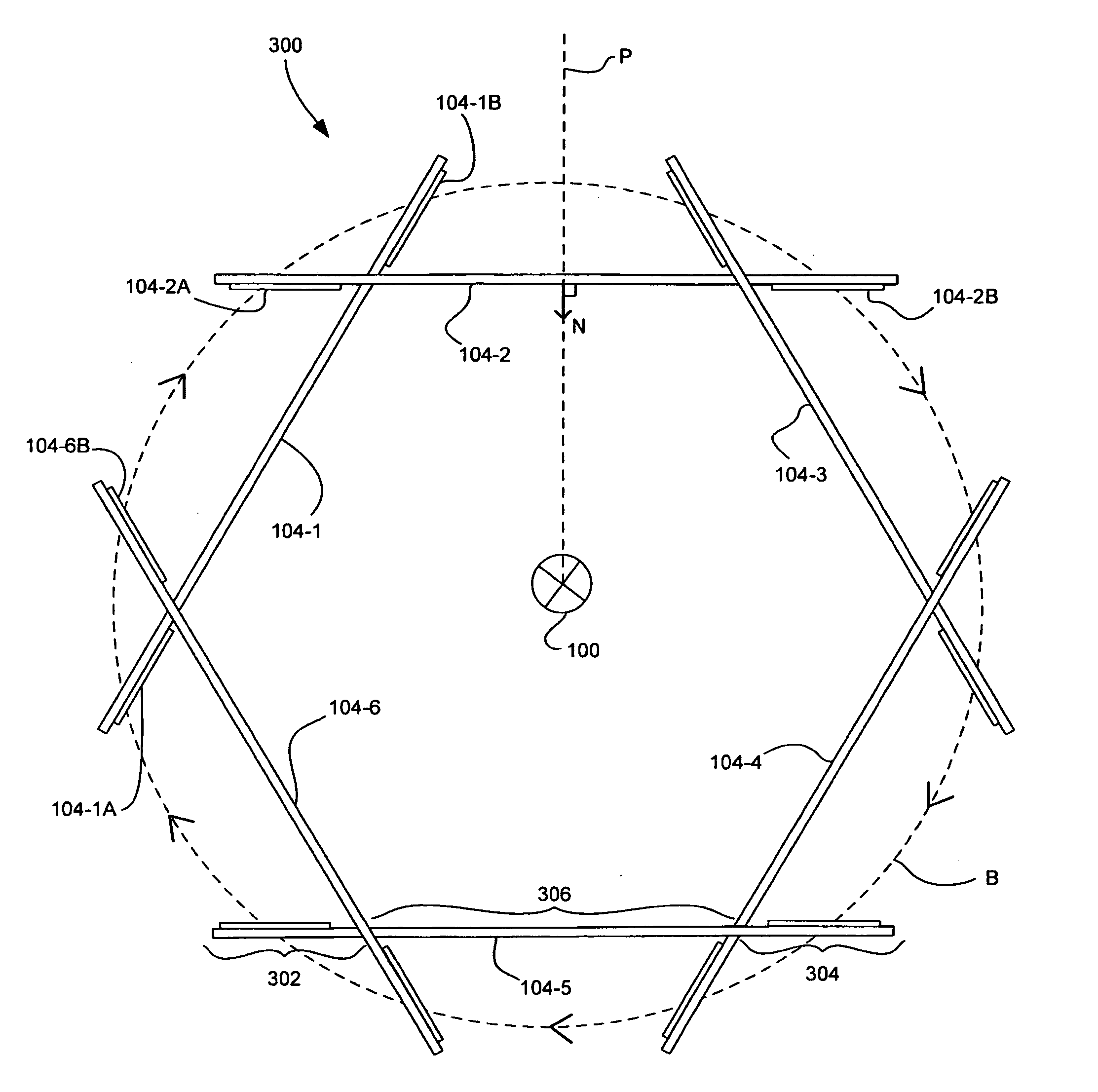
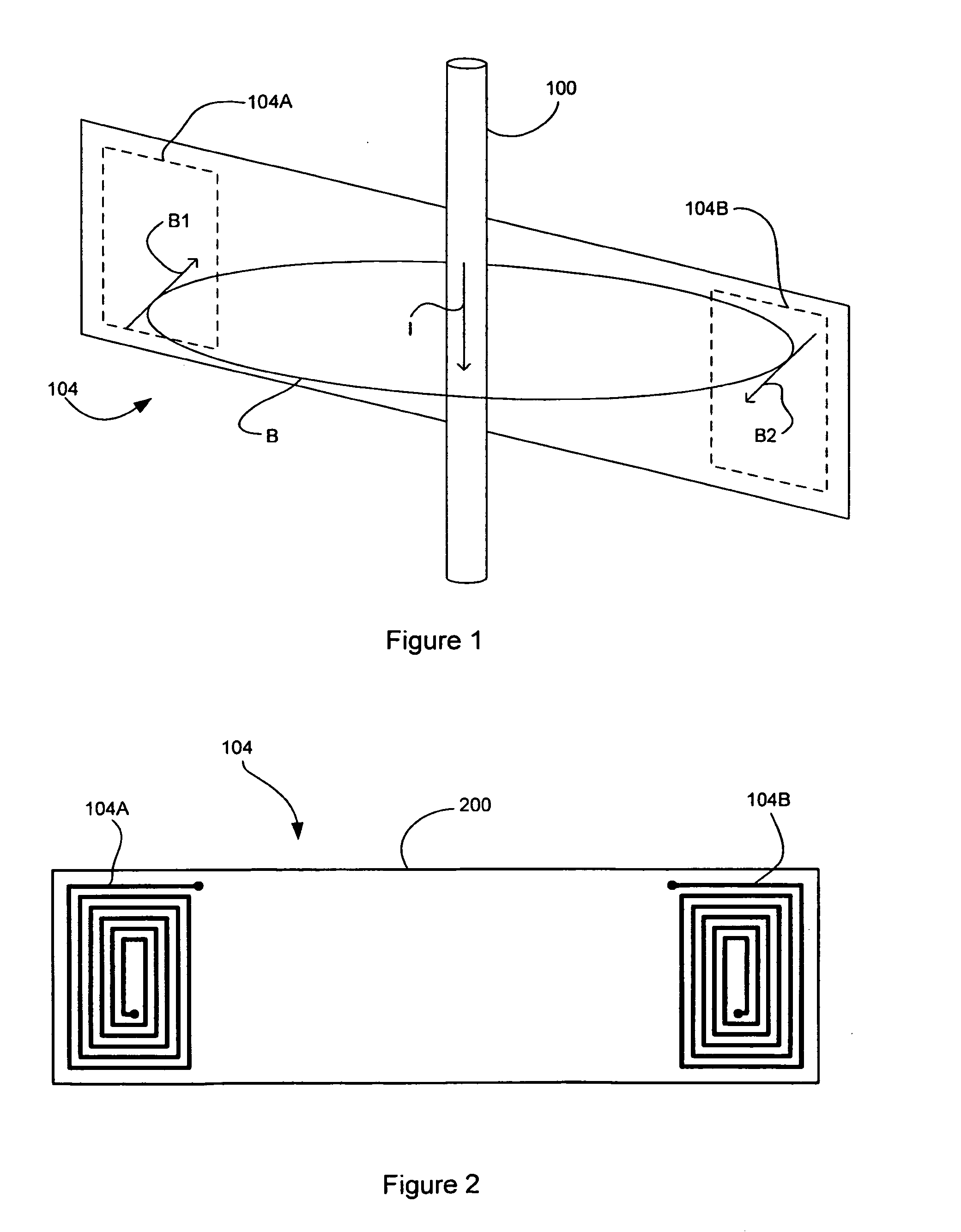
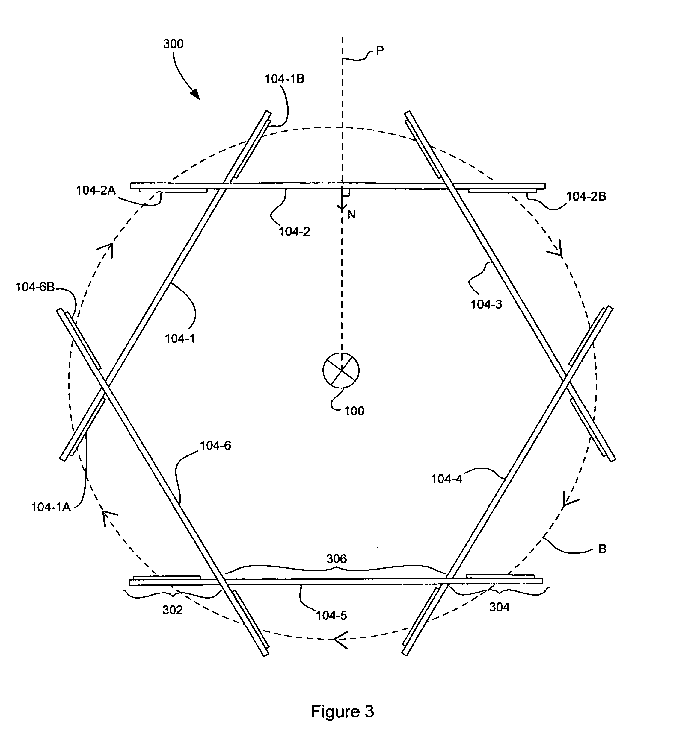
[0024]FIG. 1 depicts a primary conductor 100, a circulating magnetic field B resulting from a current I flowing through the primary conductor 10 and a schematic view of a set of two oppositely-configured sensor elements 104 of which the invention is comprised.

[0025]In FIG. 1, a current is flowing through the primary conductor 100 in a downwards direction, as denoted by the arrow labelled I. Current moving through the primary conductor 100 results in a circular magnetic field loop B surrounding the primary conductor 100. The direction of the magnetic field at particular positions on the loop B are denoted by the arrows B1 and B2.

[0026]The sensor elements 104A, 104B of the set of sensor elements 104 are configured such that when a uniform field, such as due to a distant current carrying conductor (not shown), passes through the sensor elements 104A, 104B, equal and opposite signal...


PUM


Abstract

A sensor for use in detecting a time-varying current in a conductor (106) comprises plural sets of two oppositely-configured sensor elements (104-1 . . . 104-6) arranged around a sensing volume having a central axis, the sensor elements (104-1A, 104-1B) of each set being provided substantially in a common plane that does not intersect the central axis, and each set having a different common plane, the sensor elements of each set being arranged such that a normal (N) of their common plane at a point between central parts of sensor elements lies on a plane (P) that is radial to the central axis of the sensing volume.

Description

FIELD OF THE INVENTION[0001]This invention relates to a sensor for use in detecting a time-varying current in a conductor.BACKGROUND[0002]In the field of electrical distribution, it is useful to be able to measure current flowing through conductors. Often these conductors are operated at high electric potential relative to ground and thus it is advantageous to make the measurement without direct electrical connection.[0003]It is possible to make such measurements using a current transformer. Such a device uses a magnetic circuit to couple the current in the conductor to be measured (primary conductor) and the current in a secondary conductor. This magnetic circuit typically consists of a yoke of ferromagnetic material having a conductive coil (the secondary conductor) wound therearound.[0004]There are a number of drawbacks to this kind of current sensor. The magnetic circuit may saturate either as a result of impedance in the secondary circuit, the presence of a non-time varying cur...

Claims


Application Information

Patent Timeline
Patent Type & Authority Applications(United States)
IPC IPC(8): G01R19/00
CPCG01R15/181
Inventor DAMES, ANDREWSTORKEY, MATTHEWCOLBY, EDWARDBURSTALL, OLIVER
Owner SENTIC LTD
Why Eureka
Try Eureka