Superheterodyne photonic receiver using non-serial frequency translation

a photonic receiver and superheterodyne technology, applied in the field of rf and microwave superheterodyne receivers, can solve the problems of limited dynamic range, increased noise figure, and excessive rf loss, and achieve the effect of eliminating frequency translation and reducing signal loss

Active Publication Date: 2007-09-11
LOCKHEED MARTIN CORP
View PDF5 Cites 17 Cited by
  • Summary
  • Abstract
  • Description
  • Claims
  • Application Information

AI Technical Summary

Benefits of technology

[0011]In accordance with one embodiment of the present invention, the photonic modulators can be electroabsorption waveguides as employed by Shin et al. and Kitayama. By eliminating a frequency translation device from the series RF signal path, signal loss is reduced and frequency translation is eliminated as a limitation on dynamic range. Additionally, the frequency translation device can be biased for optimum linearity while permitting the RF to optic modulator to be biased for optimum rejection of in-band spurious signal products.

Problems solved by technology

Use of a frequency translation device such as modulator 20 in series with the RF signal path results in excessive RF loss, increased noise figure, and limited dynamic range.
Also, it is difficult to remotely locate the receiver front end and deal with cables and LO distribution in actual implementation.

Method used


Image

  • Superheterodyne photonic receiver using non-serial frequency translation
  • Superheterodyne photonic receiver using non-serial frequency translation
  • Superheterodyne photonic receiver using non-serial frequency translation

Examples


Embodiment Construction

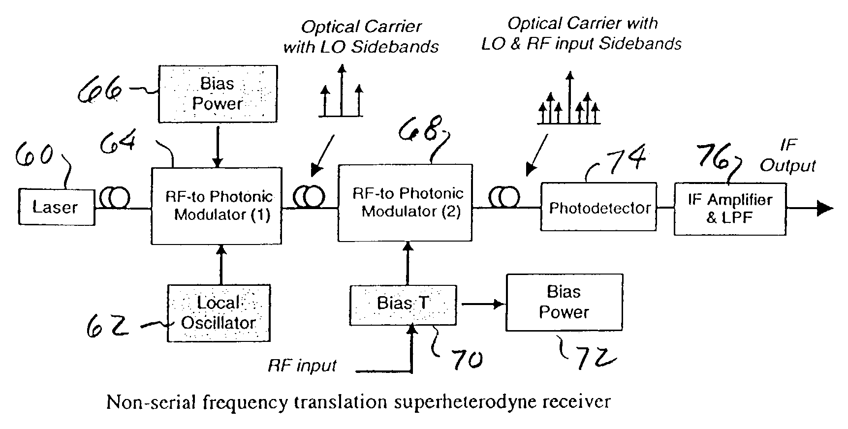
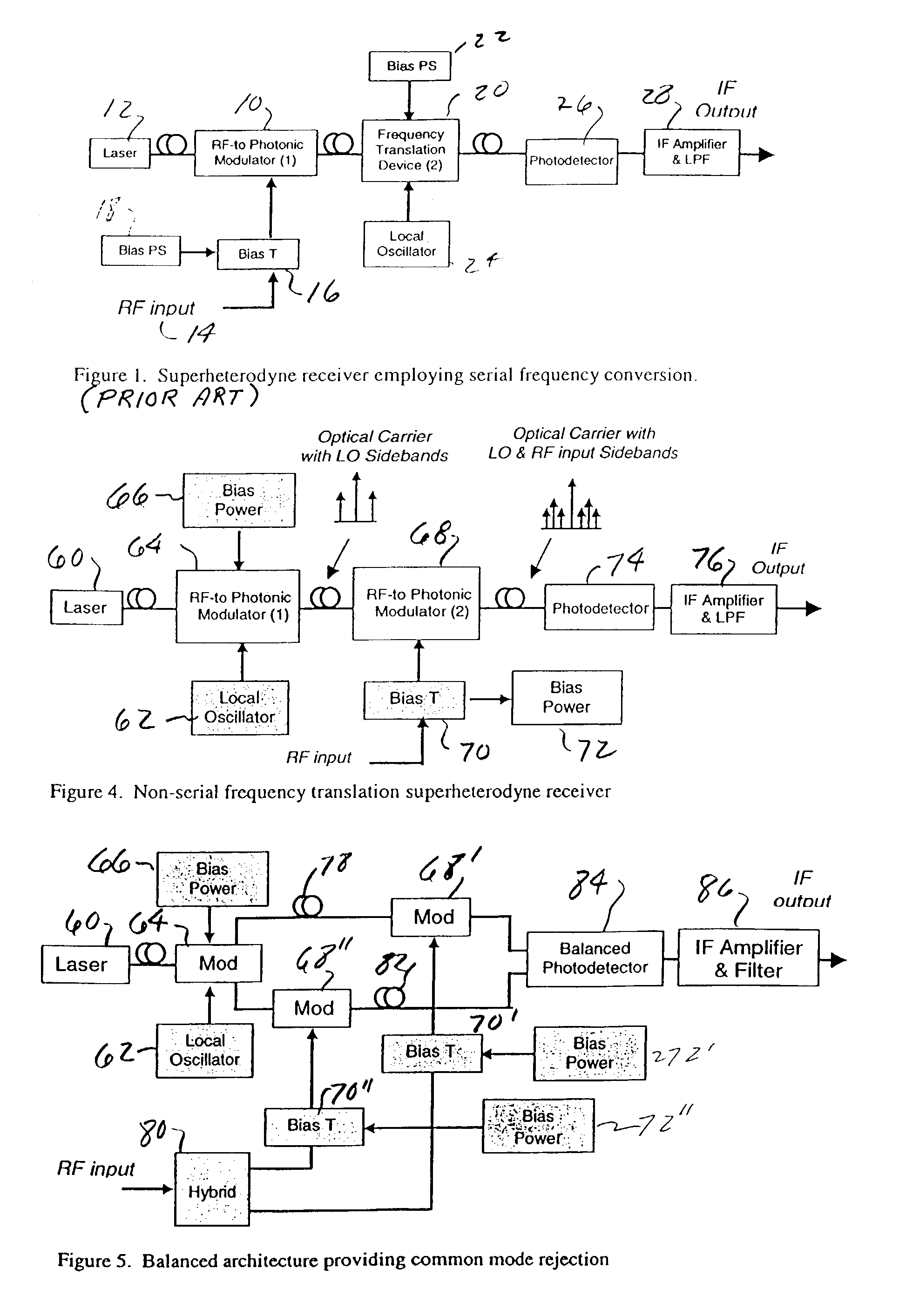
[0020]FIG. 4 is a functional block diagram of a low-loss, high-dynamic range RF receiver in accordance with one embodiment of the invention. In this embodiment, light from laser 60 is modulated with a signal from local oscillator 62 in modulator 64 which is preferably an electroabsorption waveguide modulator as known in the prior art, supra. Bias power at 66 is applied to modulator 64 for biasing for optimum linearity and producing an optical carrier with LO sidebands as illustrated. This signal is applied to a second RF to photonic modulator 68, along with the RF input which is applied through bias transistors 70 which are biased by power supply 72. Modulator 68 can be biased for optimum rejection of in-band spurious products and generates as an output the optical carrier with LO and RF input sidebands as illustrated. The IF signal is then recovered by photodetector 74 and amplifier and low pass filter 76. Modulator 68 may be biased in a number of ways independent of the bias appli...


PUM


Abstract

An optoelectronic RF signal receiver utilizes a first RF to photonic modulator for receiving an optical carrier signal and an electrical signal from a local oscillator and producing an optical carrier signal with first optical sidebands offset from the carrier signal by the local oscillator frequency. A second RF to photonic modulator receives an electrical RF signal and the signals from the first modulator and produces second sidebands to each of the first optical sidebands from the first modulator with each of the second sidebands being offset from the first sidebands by the RF signal frequency. A detector then receives signals produced by the second modulator and produces an electrical IF signal for further processing. The receiver does not utilize a frequency translation device in the RF signal path and thereby eliminates RF loss, noise, and limited dynamic range characteristic of prior art electro-optical receivers. The two modulators can be biased for optimum linearity and for optimum rejection of in-band spurious signal products.

Description

CROSS-REFERENCES TO RELATED APPLICATIONS[0001]This application claims priority to U.S. Provisional No. 60 / 420,941 filed Oct. 23, 2002, which is incorporated by reference herein.STATEMENT AS TO RIGHTS TO INVENTIONS MADE UNDER FEDERALLY SPONSORED RESEARCH OR DEVELOPMENT[0002]This invention was made with government support under Contract No. F33615-01-2-1843 awarded by the U.S. Air Force. The government has certain rights in this invention.BACKGROUND OF THE INVENTION[0003]This invention relates generally to RF and microwave superheterodyne receivers, and more particularly, the invention relates to such receivers employing photonic techniques including optoelectronic frequency translation.[0004]Optoelectronic RF receivers are used to obtain high dynamic range, wide band width signal paths, high data rates, and low mass components. Such receivers have the ability to remotely locate various parts of the receiver system and to replace heavy, bulky, and stiff transmission lines with fiberop...

Claims


Application Information

Patent Timeline
Patent Type & Authority Patents(United States)
IPC IPC(8): H04B10/00
CPCH04B10/2575H04B10/66H04B2210/006
Inventor SILVERMAN, GEORGEKARRAS, THOMAS W.
Owner LOCKHEED MARTIN CORP
Why Eureka
Try Eureka