Method for marking coagulation sites of a retina and system for coagulating the retina

a retina and coagulation site technology, applied in the field of retina coagulation site marking and retinal system, can solve the problems of increasing the speed of treatment, affecting the treatment effect, and destroying tissue worthy of preservation, so as to achieve the effect of improving the treatment speed and improving the treatment

Active Publication Date: 2012-06-14
CARL ZEISS MEDITEC AG
View PDF2 Cites 18 Cited by
  • Summary
  • Abstract
  • Description
  • Claims
  • Application Information

AI Technical Summary

Benefits of technology

[0043]With a controlled, selective retina coagulation, different absorption properties in the retinal pigment epithelium and different local transmissions of the ocular media are taken into account. As a result, locally different zones of damage of the retinal pigment epithelium can be treated.
[0044]An optoacoustic measuring system or an optical measuring system, for example, are used as temperature measuring system. By choosing a wavelength in the yellow, green, red, or infrared spectral range, a homogenous coagulation depth or hyperthermia depth can be set. Choosing equidistant individual spot distances and their diameters allows for a structuring of the homogeneity within the surface.

Problems solved by technology

However, it is hereby disadvantageous that tissue worthy of preservation, particularly the photoreceptor layer located in beam direction in front of the retinal pigment epithelium, is also destroyed.
However, such fixed patterns of regular geometry are disadvantageous because very often they do not correspond to the morphological conditions of the physiological anomalies.
Even though it is possible with the above-mentioned prior art to achieve a large pattern which leads to an increase in the speed of the treatment, the risk of overcoagulation and / or undercoagulation through the changeable focus remains due to the retinal curvature and / or varying absorption behavior of the present ocular media.

Method used


Image

  • Method for marking coagulation sites of a retina and system for coagulating the retina
  • Method for marking coagulation sites of a retina and system for coagulating the retina
  • Method for marking coagulation sites of a retina and system for coagulating the retina

Examples


Embodiment Construction

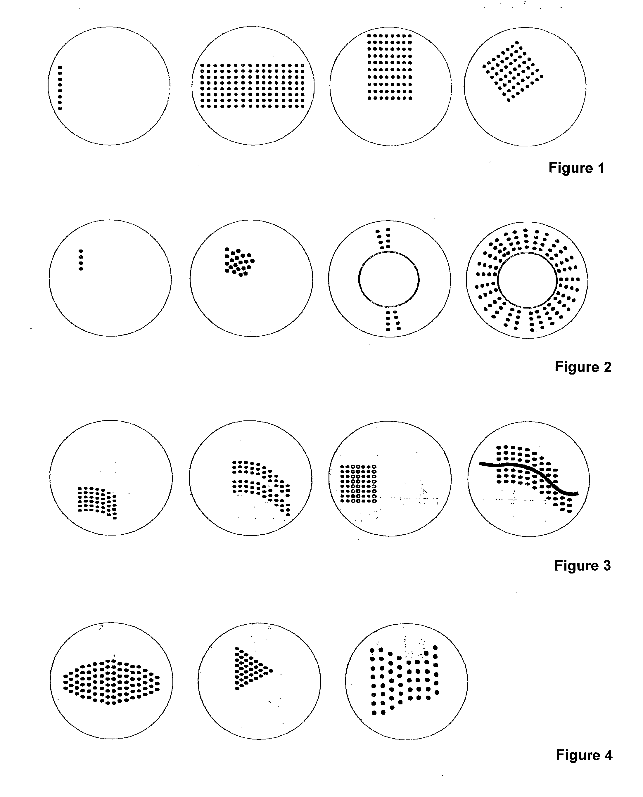
[0063]FIG. 1 shows in the first depiction from the left the basic form of a sequential, one-dimensional series of individual spots, which serves as starting point for the additional depictions of FIG. 1 and their multiple applications, as described in the following.

[0064]The series consists of eight individual spots which are arranged equidistantly to one another and run in vertical direction. The first individual spot is the depicted individual spot in the top position. Starting with said spot, the sequence is generated continuously from top to bottom in the depicted order.

[0065]Starting from said basic form, a pattern of individual spots—depicted in the second drawing from the left—arranged equidistantly to one another in a 7×16 matrix is obtained through a translation of the basic vertical series in the left drawing.

[0066]Deviating from the basic form depicted in the first drawing from the left, the sequential, one-dimensional series can also exhibit a horizontal or other directi...


PUM


Abstract

A method for marking coagulation sites on a retina by application of a light source including: projecting a serial spot sequence from a sequential, one-dimensional series of spots on the retina, wherein the individual spots indicate the coagulation sites; waiting for confirmation of the sequence of individual spots; after confirming, recalculating an automated sequence of steps having a further serial spot sequence and projecting them on the retina according to the first step; and subsequent repeating of the second and third steps. Also, a system for coagulating the retina, having an imaging diagnostic unit, a therapy beam for coagulating coagulation sites, a pilot beam for marking the coagulation sites by a spot sequence, a beam deflecting unit for generating the spot sequence and for positioning the therapy beam, an electronic control unit for controlling the above devices, a software interface, and an interactive interface.

Description

PRIORITY CLAIM[0001]The present application is a National Phase entry of PCT Application No. PCT / EP2010 / 002968, filed May 14, 2010, which claims priority from German Application No 102009021604.9, filed May 15, 2009, the disclosures of which are hereby incorporated by reference herein in their entirety.FIELD OF THE INVENTION[0002]The invention relates to a method for marking of coagulation sites on a retina by means of a light source as well as a system for coagulating the retina for executing such a method.BACKGROUND[0003]The use of focused light from an axial high-pressure lamp for the treatment of various diseases of the retina, e.g., diabetic retinopathy, by means of the light coagulation has been known for decades. Nowadays, the retina is warmed up or coagulated during light coagulation by means of a laser beam, wherein the energy of the laser beam is absorbed by the dark coloring of the pigment epithelium within the retina. As a result, the metabolism is focused on the as yet ...

Claims


Application Information

Patent Timeline
Patent Type & Authority Applications(United States)
IPC IPC(8): A61F9/007
CPCA61B18/20A61B2018/00636A61B2018/2025A61F2009/00863A61F9/008A61F9/00821A61B2019/202A61B90/13
Inventor KUNATH-FANDREI, GERALDDUNGER, JENNYFUCHS, RICODICK, MANFRED
Owner CARL ZEISS MEDITEC AG
Why Eureka
Try Eureka