
Motor drive apparatus for vehicle and motor vehicle

a technology of motor drive and motor vehicle, which is applied in the direction of engine-driven generators, electric devices, process and machine control, etc., can solve the problems of large power loss of such a motor compared to an induction motor, long time is necessary for such synchronization of the two members, and waste of energy, so as to achieve the effect of reducing energy loss and quick gear chang

Active Publication Date: 2012-06-21
NTN CORP
View PDF5 Cites 14 Cited by
  • Summary
  • Abstract
  • Description
  • Claims
  • Application Information

AI Technical Summary

Benefits of technology

[0023]The speed changing actuator assembly may further comprise a rolling bearing mounted between the control ring and the sleeve. With this arrangement, since the rotation of the control ring is not transmitted to the sleeve, gears can be changed smoothly.
[0021]In this arrangement, the transmission may further comprise a rotary member rotationally fixed to the members formed with said cam surfaces, and engaging means for rotationally fixing the respective friction plates to the rotary member when the friction plates are out of frictional engagement with the respective members formed with said cylindrical surfaces. This prevents the rollers from engaging in error due to drag torque resulting from inertia and frictional force applied to the retainer and the rollers of the two-way roller clutch while the vehicle is accelerating or decelerating.
[0024]The speed changing actuator assembly may further comprise rolling bearings mounted between the respective friction plates and the control ring. With this arrangement, it is possible to reduce frictional resistance produced between the respective friction plates and the control ring, which in turn allows smooth rotation between one of the friction plates and the control ring when the one of the friction plates is in frictional engagement with the side of the member formed with the cylindrical surface. This ensures reliable engagement of the two-way roller clutch.
[0024]The speed changing actuator assembly may further comprise rolling bearings mounted between the respective friction plates and the control ring. With this arrangement, it is possible to reduce frictional resistance produced between the respective friction plates and the control ring, which in turn allows smooth rotation between one of the friction plates and the control ring when the one of the friction plates is in frictional engagement with the side of the member formed with the cylindrical surface. This ensures reliable engagement of the two-way roller clutch.
[0019]The shift mechanism of the speed changing actuator assembly may comprise a shift rod extending parallel to the first and second shafts and movable in an axial direction of the shift rod, an actuator for moving the shift rod in the axial direction, and a shift fork supported by the shift rod and configured to move the control ring toward one of the members formed with said cylindrical surfaces together with the sleeve.
[0027]The motor drive apparatus according to the present invention includes an electric motor, a normally meshing type transmission comprising first and second shafts extending parallel to each other, and a plurality of gear trains each provided between the first and second shafts and having different gear ratios from each other. The gear trains each include a two-way roller clutch disposed between a gear of the gear train and one of the first and second shafts. The two-way roller clutches are selectively engaged and disengaged by the speed changing actuator assembly. By disengaging the two-way roller clutches, it is possible to prevent the transmission and the motor from being rotated by vehicle wheels. When this motor drive apparatus is used in a hybrid vehicle to drive auxiliary vehicle wheels, it is possible to minimize energy loss while the vehicle is being driven by the engine.
[0019]The shift mechanism of the speed changing actuator assembly may comprise a shift rod extending parallel to the first and second shafts and movable in an axial direction of the shift rod, an actuator for moving the shift rod in the axial direction, and a shift fork supported by the shift rod and configured to move the control ring toward one of the members formed with said cylindrical surfaces together with the sleeve.

Problems solved by technology

This leads to a waste of energy.
Especially if the motor is a permanent magnet type synchronous motor, large power is lost to rotate such a motor compared to an induction motor.
A long time is necessary for such synchronization of the two members.
This deteriorates drivability of the vehicle and also lowers its commercial value.

Method used


Image

  • Motor drive apparatus for vehicle and motor vehicle
  • Motor drive apparatus for vehicle and motor vehicle
  • Motor drive apparatus for vehicle and motor vehicle

Examples


Embodiment Construction

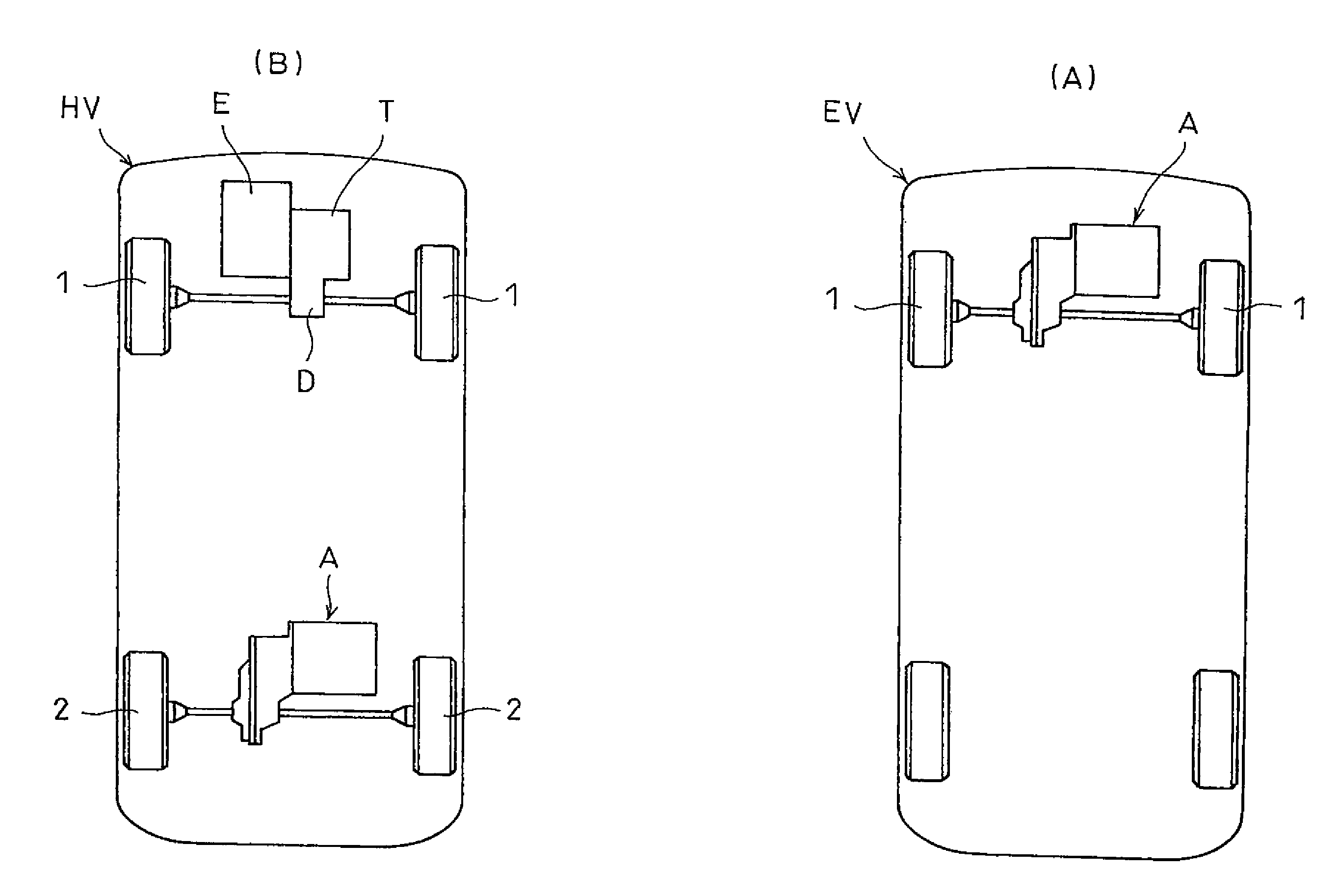
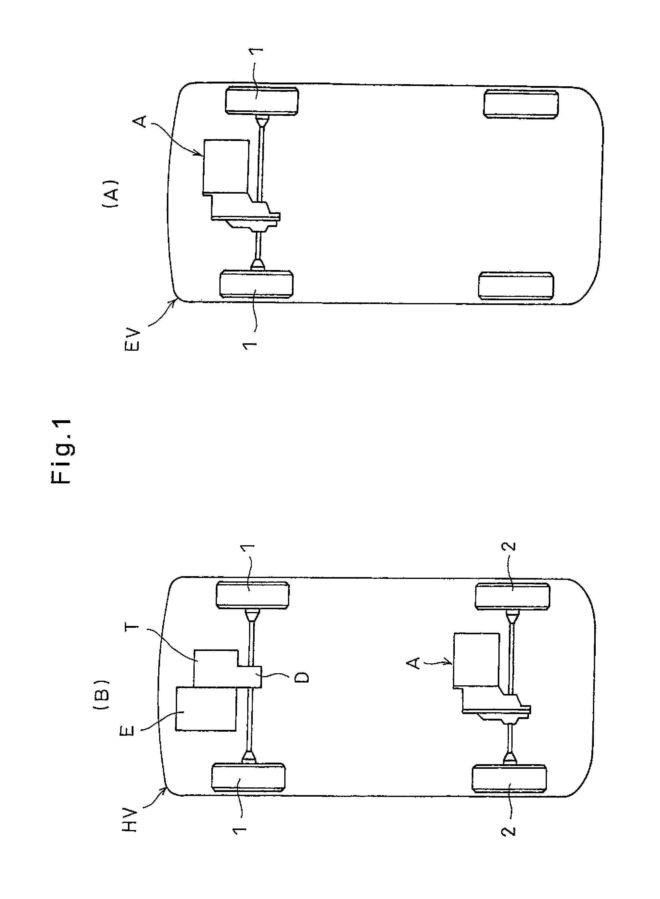
[0043]The embodiment of the present invention is now described with reference to the drawings. FIG. 1(A) shows an electric vehicle EV including a motor drive apparatus A according to the present invention, which is configured to drive the right and left front wheels 1 of the vehicle. FIG. 1(B) shows a hybrid vehicle HV including an engine E configured to drive the right and left front wheels of the vehicle, and the motor drive apparatus A according to the present invention configured to drive the right and left rear wheels 2 of the vehicle. The revolution of the engine E is transmitted to the front wheels 1 through a transmission T and a differential gear assembly D.

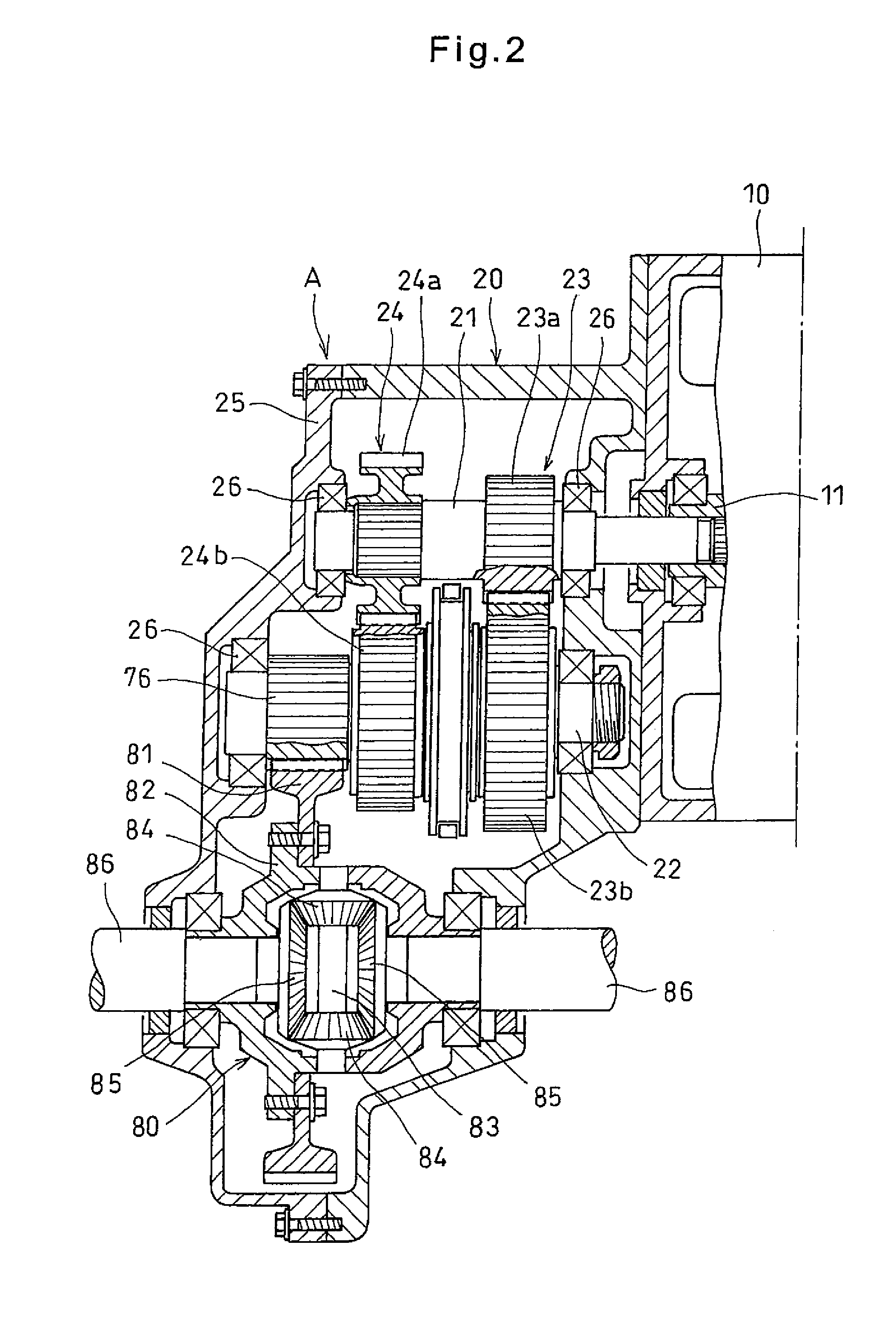
[0044]As shown in FIG. 2, the motor drive apparatus A comprises an electric motor 10 having an output shaft 11, a transmission 20 for changing the rotational speed of output shaft 11 of the electric motor 10, and a differential gear assembly 80 for distributing the power from the transmission 20 to the right and left fro...


PUM


Abstract

A motor drive apparatus for a vehicle is provided which can prevent its transmission and motor from being rotated by vehicle wheels, and which allows quick gear change. This apparatus includes an electric motor (10), a first shaft (21) driven by the electric motor (10), a second shaft (22), first and second reduction gear trains (23 and 24) disposed between the first and second shafts (21 and 22). Two-way roller clutches (30A and 30B) are mounted between a first output gear (23b) of the first reduction gear train (23) and the second shaft (22) and between a second output gear (24b) of the second reduction gear train (24) and the second shaft (22), respectively. Gear changes are made by selectively engaging and disengaging the two-way roller clutches (30A and 30B) with a speed changing mechanism (50).

Description

TECHNICAL FIELD[0001]This invention relates to a motor drive apparatus for a vehicle including an electric motor as a driving source and adapted to transmit the output of the electric motor to wheels after reducing its speed, and a motor vehicle carrying such a motor drive apparatus.BACKGROUND ART[0002]Conventional motor drive apparatus used to drive electric vehicles and hybrid vehicles are shown in Patent documents 1 and 2. The motor drive apparatus disclosed in Patent document 1 includes a motor, and a transmission comprising a belt type continuously variable transmission (CVT) or a planetary gear transmission in which the rotational speed of the motor is changed and transmitted to a differential gear assembly, through which the power is distributed to right and left auxiliary (rear) drive wheels.[0003]The motor drive apparatus disclosed in Patent document 2 includes a motor, and a transmission comprising a planetary gear transmission in which the rotational speed of the motor is...

Claims


Application Information

Patent Timeline
IPC IPC(8): B60L15/00B60K1/00B60K6/54F16H37/04B60L50/15B60L50/16F16H48/08
CPCB60K1/00Y02T10/7275B60K6/52B60K6/547B60K17/165B60K17/356B60K2001/001F16D41/088F16D2500/10493F16H3/10F16H48/08F16H63/30F16H2063/3093F16H2200/0021F16H2200/0034Y02T10/6265B60L11/123B60L11/14B60L15/20B60L2220/14B60L2240/421B60L2240/423B60L2260/28Y02T10/6217B60K6/383Y02T10/72B60L50/61B60L50/16Y02T10/62Y02T10/70
Inventor MAKINO, TOMOAKI
Owner NTN CORP
Learn More