Fire-control system

a control system and fire control technology, applied in the field of fire control systems, can solve the problems of introducing further limitations, unable to aim, and generally not suffice normal sight, and achieve the effect of raising awareness of events

Active Publication Date: 2012-06-28
AIMPOINT AB
View PDF15 Cites 46 Cited by
  • Summary
  • Abstract
  • Description
  • Claims
  • Application Information

AI Technical Summary

Benefits of technology

[0007]When using high-trajectory ammunition in a field condition it is obviously important to maintain an elevated awareness regarding the events in the surroundings. Therefore it is beneficial and desired to have a fire-control system that does not include optics or electronics distorting

Problems solved by technology

A normal sight will generally not suffice, since it is difficult or impossible to have a visual contact with the target via the sight and at the same time have the correct inclination of the barrel, thus aiming is impossible.
Also the sight may need to cover a considerable interval of inclinations, which introduces further limitations.
Thoug

Method used


Image

  • Fire-control system
  • Fire-control system
  • Fire-control system

Examples


Embodiment Construction

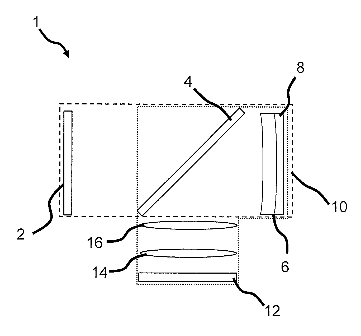
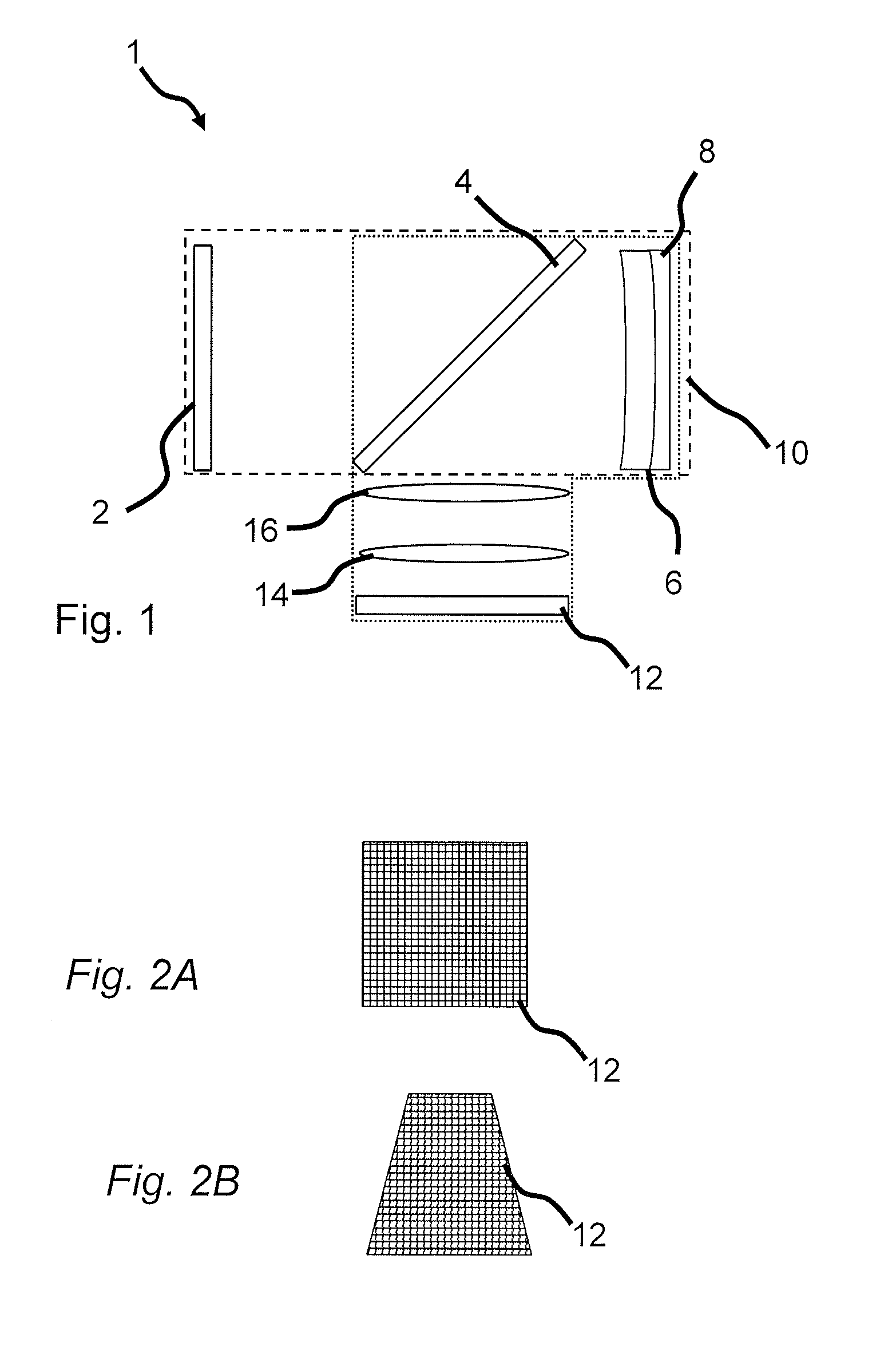
[0040]The general structure and function of the inventive fire-control system in the embodiment of a sight 1 is described referring to FIG. 1, which is a schematic representation of the sight, as viewed from one side. In the depicted view a target would be situated to the right, and the user to the left. The user may observe the target directly through a light channel housing an entrance window 2, an angled narrow-banded reflector 4, a dual lens system 6, 8, and a protective exit window 10 having essentially the same purpose as the entrance window 2. The entrance window 2 may also consist of a lens, which may be used to correct for possible distortions. All components will be defined in the following, and one important feature of the optical components are that they do not disturb the light path from the target to the eye of the user to any significant degree, by introducing distortion. It is also to be understood that the sight 1 as such is non-magnifying. A user may therefore obse...


PUM


Abstract

A fire-control system comprising -a housing, -a light channel, through which a user may directly observe a target and receive visually displayed information simultaneously, said light channel comprising partially reflective optics a light source, for visualization of a reticle to the user via the partially reflective optics, -means for receiving a measure of the distance to the target a processor, for determining the adequate position of the reticle, based on the distance to the target, and for controlling the light source to emit light so that the reticle is visualized at the adequate position, wherein the light source is an array capable of selectively emitting light in well defined locations on its surface.

Description

FIELD OF THE INVENTION[0001]The present invention relates to a fire-control system, and in particular to a fire-control system adapted for use with a weapon firing ammunition with a relatively high trajectory or firing with low-trajectory ammunition at longer distances. The invention also relates to a method of displaying a reticle and to a computer program for executing said method.TECHNICAL BACKGROUND[0002]When using ammunition with low exit velocity, high trajectory or firing at targets at a significant distance, where the time of flight is significant, the weapon sight has to have certain properties. In such conditions the barrel of the weapon needs to have a considerable elevation in order for the ammunition to reach the target. A normal sight will generally not suffice, since it is difficult or impossible to have a visual contact with the target via the sight and at the same time have the correct inclination of the barrel, thus aiming is impossible. Also the sight may need to ...

Claims


Application Information

Patent Timeline
IPC IPC(8): F41G1/473G02B23/10F41G3/10F41G3/08F41G1/30F41G3/06
CPCF41G1/30F41G3/08F41G3/06F41G1/473F41G3/14G02B23/105G02B2027/0129G02B27/36F41G3/005
Inventor HAKANSON, HAKANWIKLUND, RALFGUNNARSSON, KJELLBRANDT, MIKAELTRULSSON, HAKAN
Owner AIMPOINT AB
Why Eureka
Try Eureka