Method and apparatus for monitoring fluids

Inactive Publication Date: 2012-06-28
PARADIGM FLOW SERVICES
View PDF0 Cites 30 Cited by
  • Summary
  • Abstract
  • Description
  • Claims
  • Application Information

AI Technical Summary

Benefits of technology

[0045]By having the monitoring zone configured to provide upstream fluid cooperation with an entrance to the fluid conduit allows the fluid monitoring unit to dynamically monitor the fluid supply prior

Problems solved by technology

During the production and transportation of hydrocarbons, it is common for the interiors of fluid conduits, including pipelines, wellbores, risers and umbilicals, to become fouled.
This fouling can lead to the build up of layers of debris or particulate matter on the inside of conduits, which reduces the effective inner diameter (ID) of the conduit and thus reduces the flow rate.
Fouling can also produce blockages in the fluid conduits which completely prevent fluid flow.
The relatively small diameters of the internal tubes within the subsea umbilical, in combination with the fact that their helical path arrangement significantly increases the frictional drag experienced by objects inserted into the internal tubes, means that umbilicals are particularly prone to blockages.
Such blockages completely prevent fluid transmission through the umbilical and so can cause considerable disru

Method used


Image

  • Method and apparatus for monitoring fluids
  • Method and apparatus for monitoring fluids
  • Method and apparatus for monitoring fluids

Examples


Example

[0070]In the description which follows, like parts are marked throughout the specification and drawings with the same reference numerals. The drawings are not necessarily to scale and the proportions of certain parts have been exaggerated to better illustrate details and features of embodiments of the invention.

DETAILED DESCRIPTION

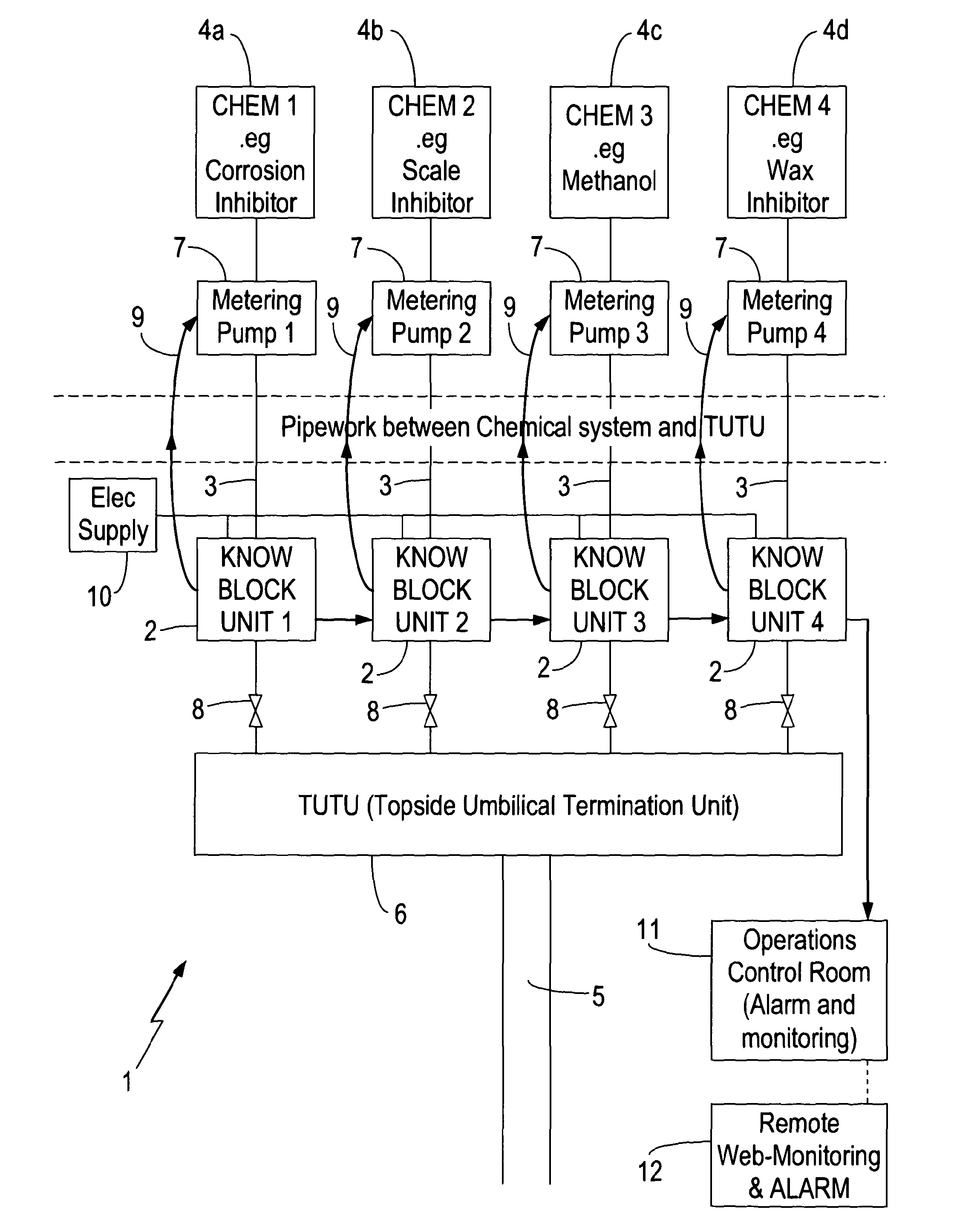
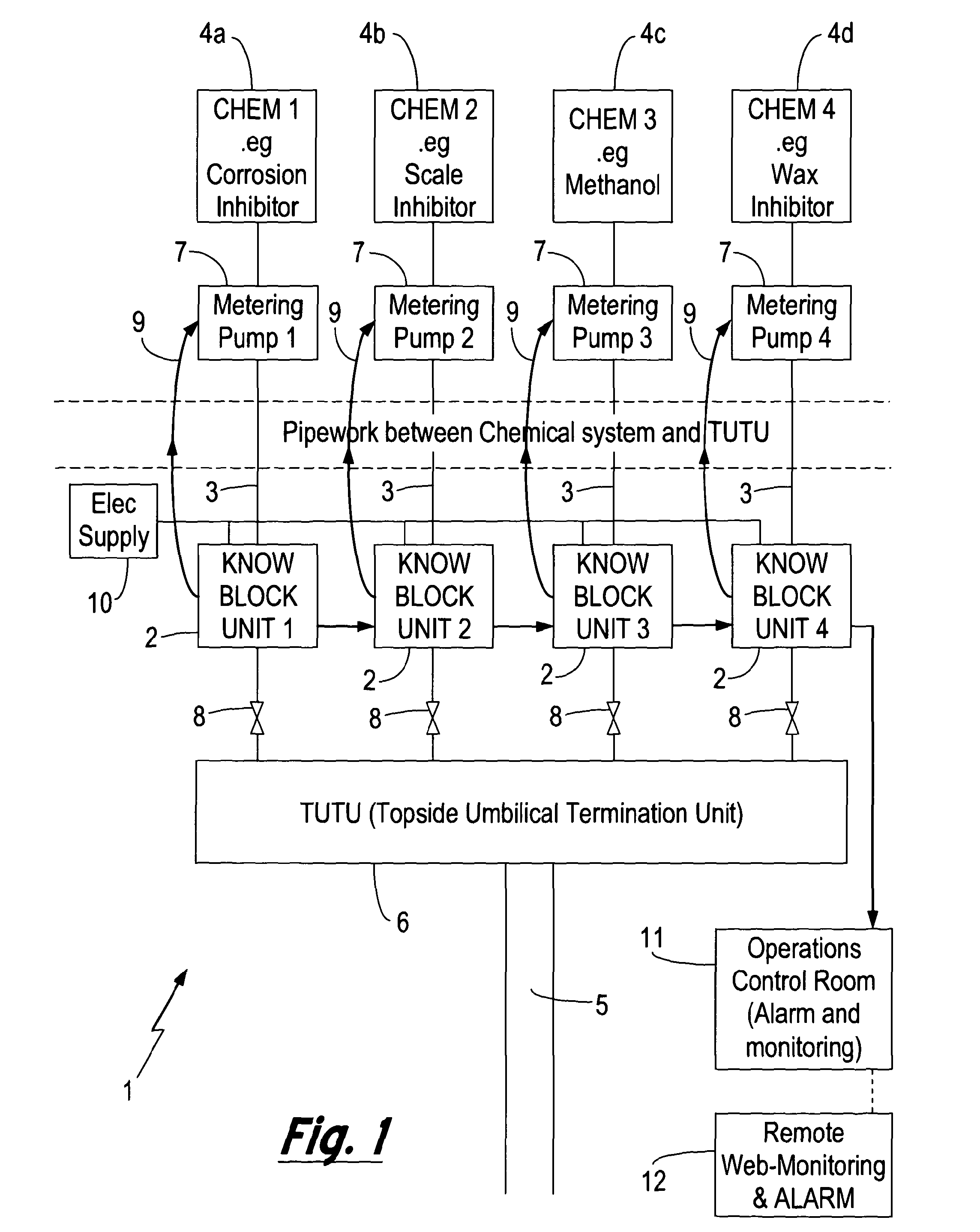
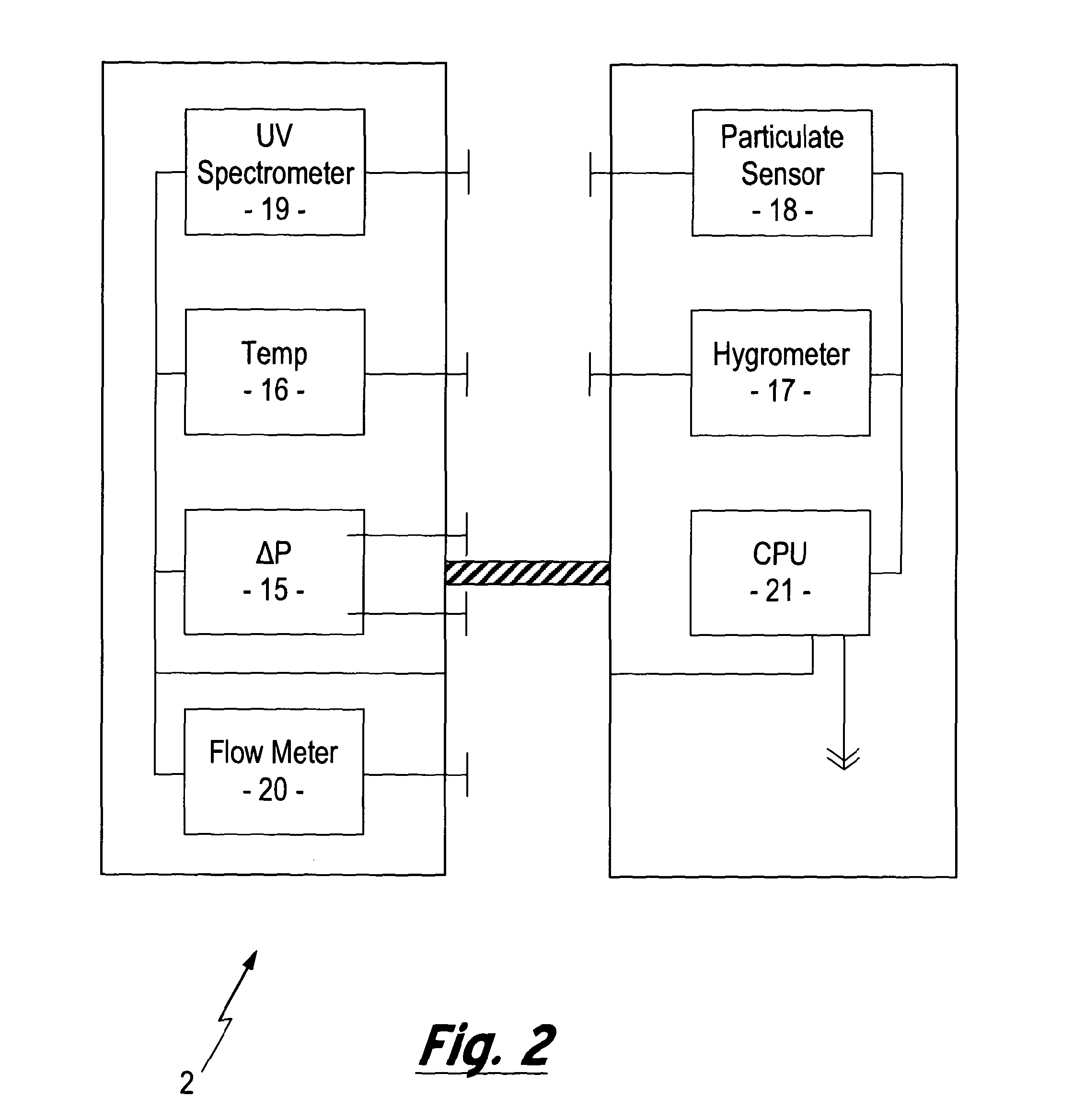
[0071]In order to provide understanding of the various aspects of the present invention a schematic diagram of a surface production facility, generally depicted by the reference numeral 1, is presented in FIG. 1, while FIG. 2 presents a schematic diagram of a fluid monitoring unit 2 employed with the surface production facility 1.

[0072]The surface production facility 1 can be seen to comprise four supply conduits 3 that provide a means for fluid communication between a corresponding fluid source 4 and an umbilical 5 via a topside umbilical termination unit (TUTU) 6. In the presently described embodiment the fluid sources comprise a corrosion inhibitor 4a (...


PUM


Abstract

A method and apparatus for monitoring a fluid that is to be transported through a fluid conduit within a hydrocarbon exploration and production installation is described. A monitoring zone is established upstream of the fluid conduit configured such the fluid supply to the fluid conduit is introduced via the monitoring zone. The fluid supply within the monitoring zone is monitored for the occurrence of events detrimental to the flow of the fluid supply through the fluid conduit. Monitoring the fluid supply prior to entering the fluid conduit allows for the early detection of an event detrimental to the flow of the fluid supply e.g. a chemical reaction indicative of corrosion of the fluid conduit or the formation of a potential blockage within the fluid conduit. In this way the risk of costly blockages or structural failure occurring within the fluid conduit is reduced.

Description

[0001]The present invention relates to a method and apparatus for use in the hydrocarbon exploration and production industry and in particular to a method and apparatus for monitoring a fluid that is to be transported through a fluid conduit. The monitoring of a fluid to be transported through a fluid conduit provides a dynamic indication of the occurrence of detrimental effects for the fluid flow within the conduit. The described method and apparatus have particular application for preventing blockages within fluid umbilicals, although the methods and apparatus may also be adapted for monitoring fluids for the occurrence of detrimental effects within pipelines, wellbores and risers.[0002]During the production and transportation of hydrocarbons, it is common for the interiors of fluid conduits, including pipelines, wellbores, risers and umbilicals, to become fouled. This fouling can lead to the build up of layers of debris or particulate matter on the inside of conduits, which reduc...

Claims


Application Information

Patent Timeline
IPC IPC(8): F17D1/00G01N15/06G01N37/00F16K15/00G01J3/28G06F19/00G08B21/00G01N11/00G01N25/00E21B47/00
CPCE21B47/0001E21B43/01E21B47/001Y10T137/0318Y10T137/7837E21B21/08E21B47/10
Inventor MACKENZIE, HUGHBAIN, ROBERT
Owner PARADIGM FLOW SERVICES
Why Eureka
Try Eureka