Superconducting electric motor

a superconducting electric motor and superconducting wire technology, applied in the direction of magnetic circuit rotating parts, magnetic circuit shapes/forms/construction, windings, etc., can solve the problem of difficult to improve cooling efficiency, superconducting wire material generally used as a superconducting coil has an extremely poor thermal conductivity, and the effect of reducing or eliminating the difference in length

Inactive Publication Date: 2012-06-28
TOYOTA JIDOSHA KK
View PDF34 Cites 15 Cited by
  • Summary
  • Abstract
  • Description
  • Claims
  • Application Information

AI Technical Summary

Benefits of technology

[0023]With the superconducting electric motor according to the aspect of the invention, at least part of each of the plurality of narrow tubes that are provided for the refrigerator and that flow low-temperature refrigerant inside are provided in the stator core, so the plurality of superconducting coils may be efficiently cooled to a desired cryogenic temperature. In addition, the one-side connecting portion and the other-side connecting portion that are refrigerant supply/drain connecting portions at both ends of each of the plurality of narrow tubes are respectively provided on both axial sides of the stator at opposite si

Problems solved by technology

As in the case of the superconducting electric motor described in JP-A-2010-178517, in an existing art, cold is transferred by various methods when the superconducting coils are cooled; however, when the solid heat conductive materials are used to cool the superconducting coils, the thermal conductivity of each heat conductive material is finite, so, when heat is transferred through the heat conductive materials having a finite length, there occurs a temperature difference proportional to the amount of heat transferred and, therefore, it is difficult to improve cooling efficiency.
However, even in this case, there occurs a delay in response of heat transfer from the output of the refrigerator to the superconducting coils during a high load or in a transitional motor operating state in which the load steeply increases, and the temperature of the superconduct

Method used


Image

  • Superconducting electric motor
  • Superconducting electric motor
  • Superconducting electric motor

Examples


first embodiment

[0042]Hereinafter, an embodiment of the invention will be described in detail with reference to the accompanying drawings. In this description, specific shapes, materials, numeric values, directions, and the like, are only illustrative for easily understanding the aspect of the invention and may be modified appropriately to meet an application purpose, an object, specifications, and the like.

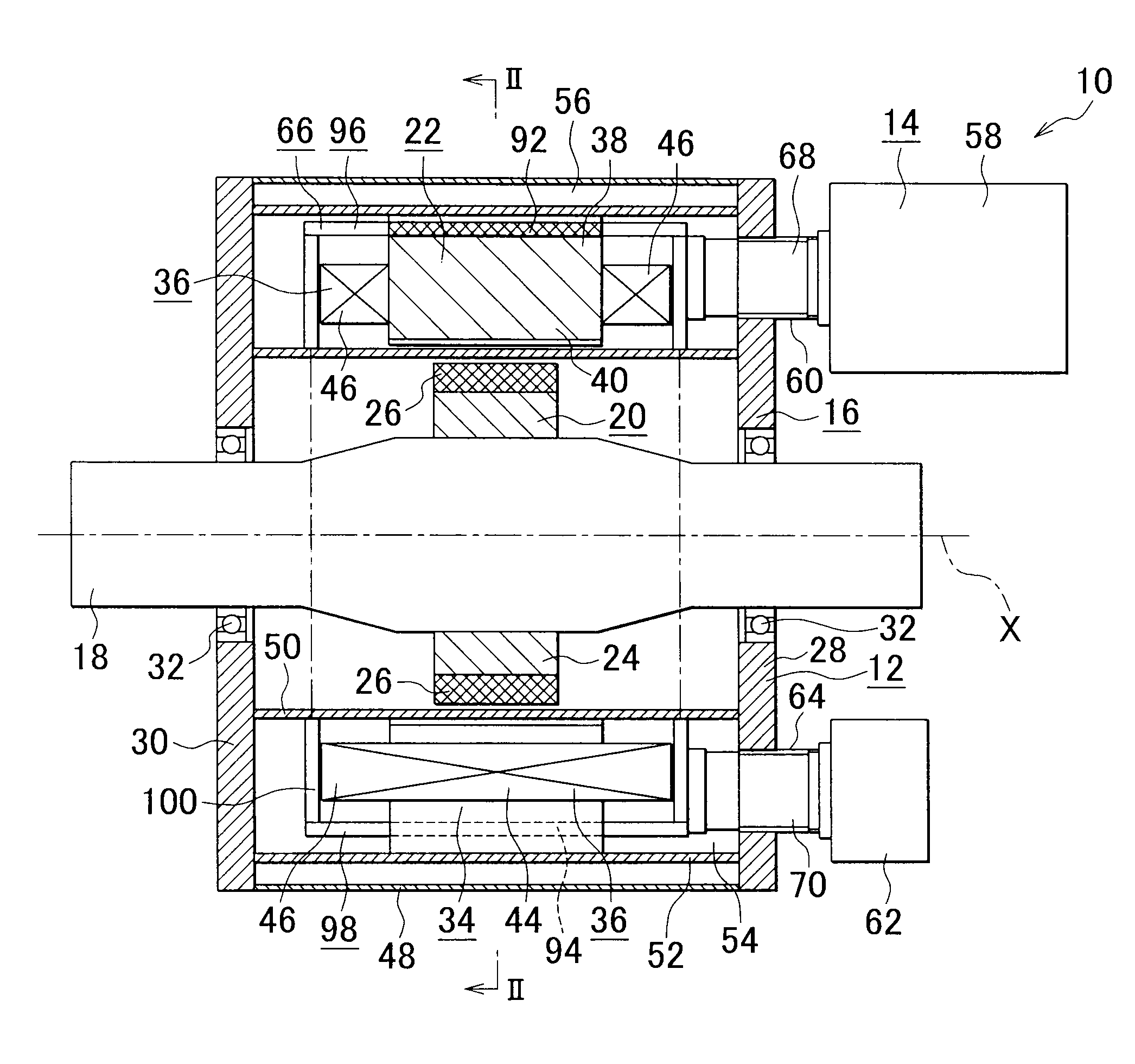
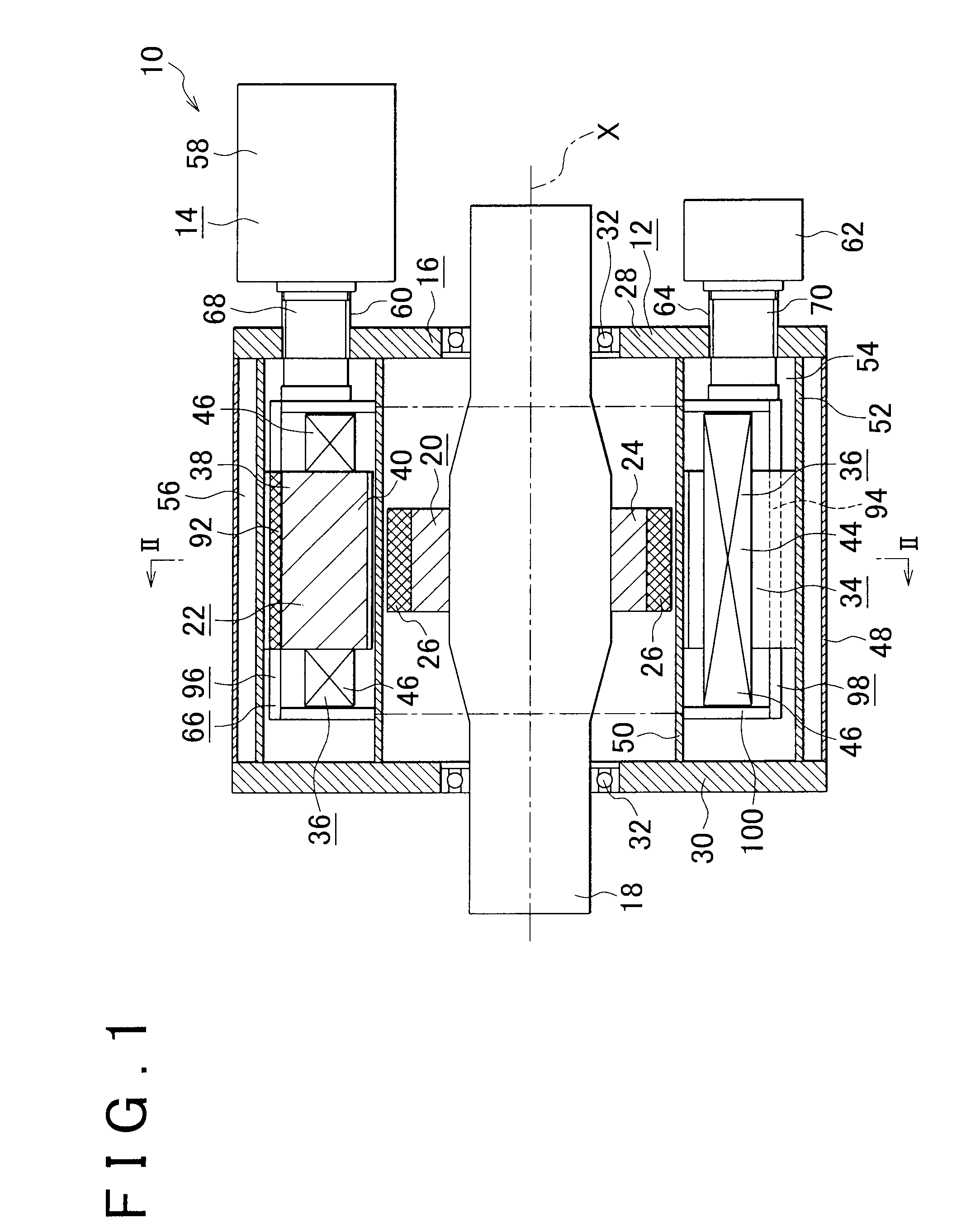
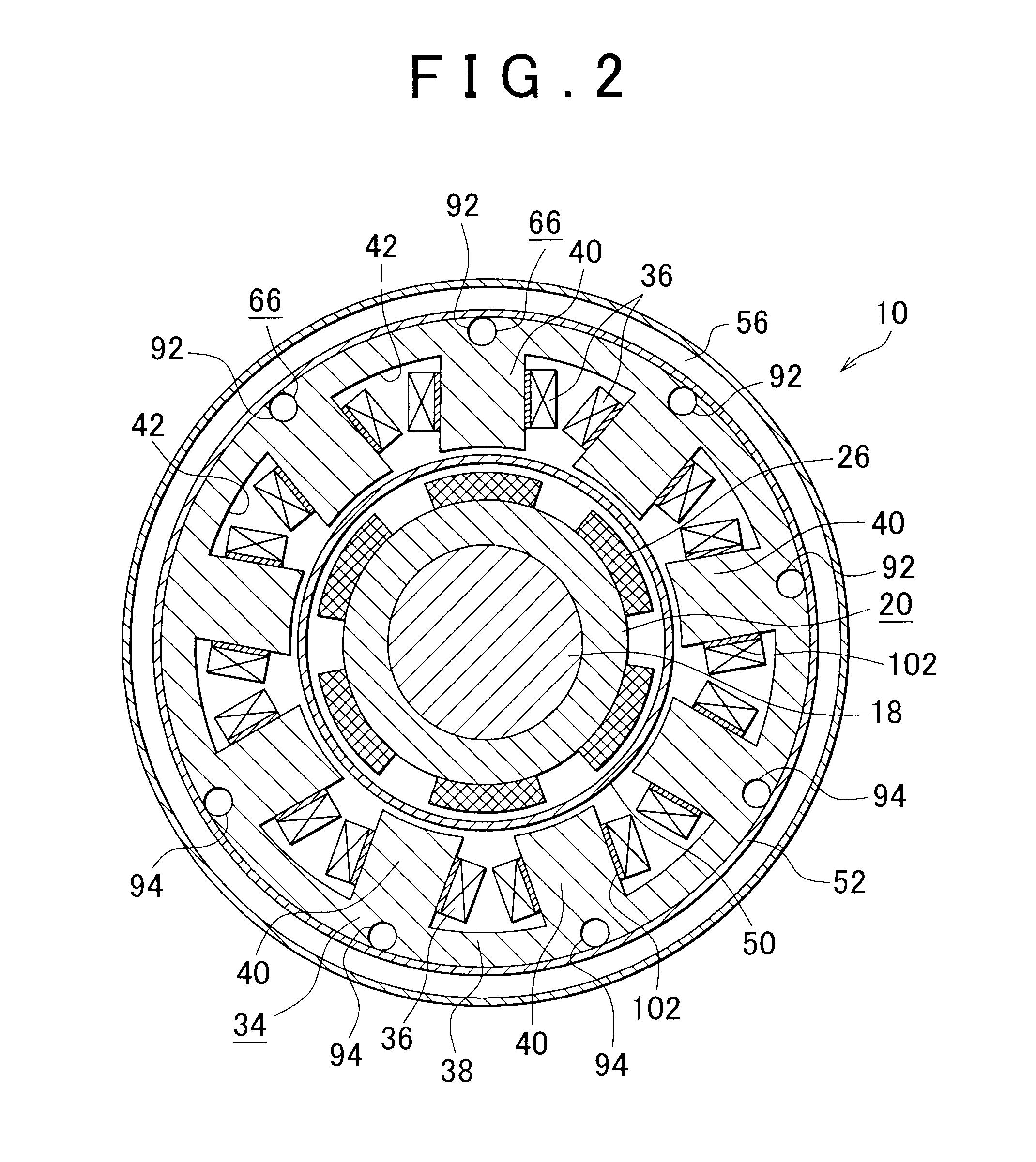
[0043]FIG. 1 to FIG. 4 show a superconducting electric motor according to a first embodiment of the invention. As shown in FIG. 1 and FIG. 2, the superconducting electric motor 10 includes a motor body 12 and a refrigerator 14. The refrigerator 14 is used to cool the motor body 12. The motor body 12 includes a motor case 16, a rotary shaft 18 and a rotor 20. The rotary shaft 18 is rotatably supported by the motor case 16. The rotor 20 is fixed to the outer side of the rotary shaft 18 inside the motor case 16 and is rotatably arranged. In addition, the motor body 12 includes a substantially cylin...

second embodiment

[0074]FIG. 7 is an axially cross-sectional view that shows a superconducting electric motor according to a second embodiment of the invention. FIG. 8 is a cross-sectional view that is taken along the line VIII-VIII in FIG. 7.

[0075]The superconducting electric motor 10 according to the present embodiment differs from that of the first embodiment in that the plurality of narrow tubes 66 each have a crank-shaped portion that is formed to bend in a crank shape instead of the straight portions 96 and 98 (see FIG. 1, and the like). That is, the plurality of narrow tubes 66 each have a first core penetrating portion 104 and a second core penetrating portion 106 that are provided at two positions in the longitudinal center portion of the narrow tube 66. The core penetrating portions 104 and 106 are provided in some of the plurality of teeth 40 of the stator core 34 so as to axially penetrate through substantially the center portion of corresponding teeth 40 of the stator core 34.

[0076]That ...

third embodiment

[0078]FIG. 9 is an axially cross-sectional view that shows a superconducting electric motor according to a third embodiment of the invention. FIG. 10 is a cross-sectional view that is taken along the line X-X in FIG. 9.

[0079]The superconducting electric motor 10 according to the present embodiment has a configuration that combines the second embodiment shown in FIG. 7 and FIG. 8 with the first embodiment shown in FIG. 1 to FIG. 4. That is, in the third embodiment, the refrigerator 14 has first narrow tubes 114 and second narrow tubes 116 that flow low-temperature refrigerant gas inside. The plurality of first narrow tubes 114 and the plurality of second narrow tubes 116 are provided. Each of the first narrow tubes 114 has a configuration similar to that of each of the narrow tubes 66 (FIG. 1 and FIG. 2) that constitute the refrigerator 14 of the first embodiment, and has two first core penetrating portions 118 that are provided so as to axially penetrate through at two positions dif...


PUM


Abstract

A superconducting electric motor includes: a rotor rotatably arranged; a stator arranged in a radial direction of the rotor to face the rotor; and a refrigerator having at least one narrow tube that flows low-temperature refrigerant inside. The stator has a plurality of superconducting coils wound at a radial end portion of a stator core and formed of a superconducting wire material. The at least one narrow tube has a core penetrating portion that is provided to penetrate through the stator core. Alternatively, the refrigerator has a plurality of narrow tubes, and at least part of each narrow tube is provided in the stator core. Connecting portions that are refrigerant supply/drain connecting portions at both ends of each of the plurality of narrow tubes are provided on both axial sides of the stator at opposite sides in a diametrical direction with respect to a rotation central axis of the rotor.

Description

INCORPORATION BY REFERENCE[0001]The disclosures of Japanese Patent Applications No. 2010-292502 filed on Dec. 28, 2010 and No. 2010-292801 filed on Dec. 28, 2010 including the specification, drawings and abstract are incorporated herein by reference in its entirety.BACKGROUND OF THE INVENTION[0002]1. Field of the Invention[0003]The invention relates to a superconducting electric motor and, more particularly, to a superconducting electric motor that includes a refrigerator having at least one narrow tube that flows low-temperature refrigerant inside.[0004]2. Description of Related Art[0005]In an existing art, a superconducting electric motor that includes a refrigerator is suggested. For example, Japanese Patent Application Publication No. 2010-178517 (JP-A-2010-178517) describes a superconducting electric motor apparatus that includes a superconducting electric motor, a cryogenic temperature generator and a casing. The superconducting electric motor includes a rotor and a stator. Th...

Claims


Application Information

Patent Timeline
IPC IPC(8): H02K1/20
CPCH02K1/20H02K3/24H02K55/02
Inventor MIZUTANI, RYOJIOHASHI, YOSHIMASAOKUMURA, NOBUOISHIDA, KENJI
Owner TOYOTA JIDOSHA KK
Why Eureka
Try Eureka