Reflectarray antenna system

Inactive Publication Date: 2012-06-28
FUNDACIO PRIVADA CENT TECNOLOGIC DE TELECOMUNICACIONS DE CATALUNYA
View PDF5 Cites 36 Cited by
  • Summary
  • Abstract
  • Description
  • Claims
  • Application Information

AI Technical Summary

Benefits of technology

[0021]In order to overcome the limitations in the prior art described above, the present invention takes advantage of the synchronization properties of inje

Problems solved by technology

Such a topology may lead to problems when designing a reflectarray due to available space limitation, in order to maintain a typical 0.5-0.65 free space wavelengths distance among the

Method used


Image

  • Reflectarray antenna system
  • Reflectarray antenna system
  • Reflectarray antenna system

Examples


Embodiment Construction

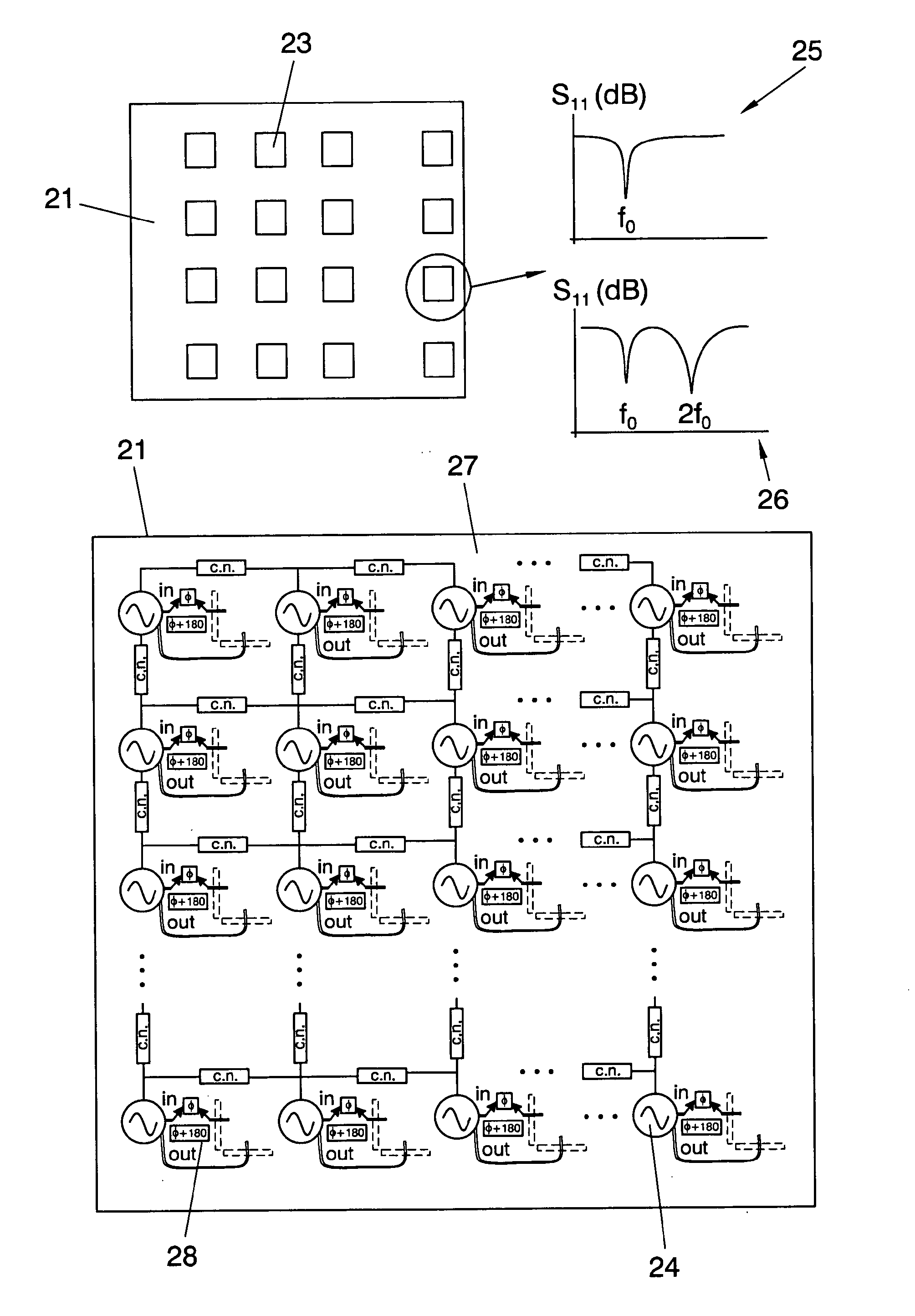
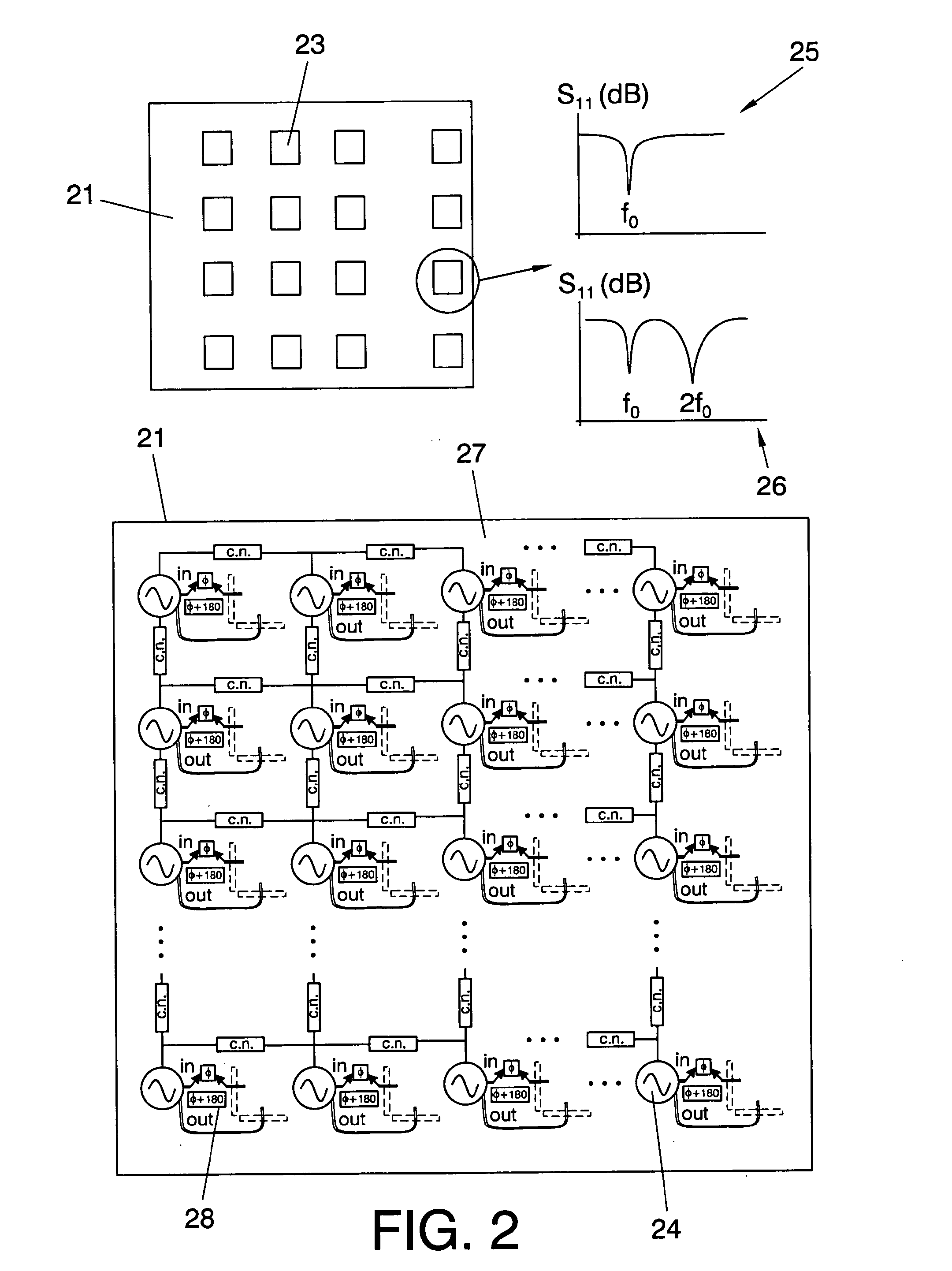
[0099]Here below some practical implementations of a reflectarray in accordance to different embodiments of the invention are described.

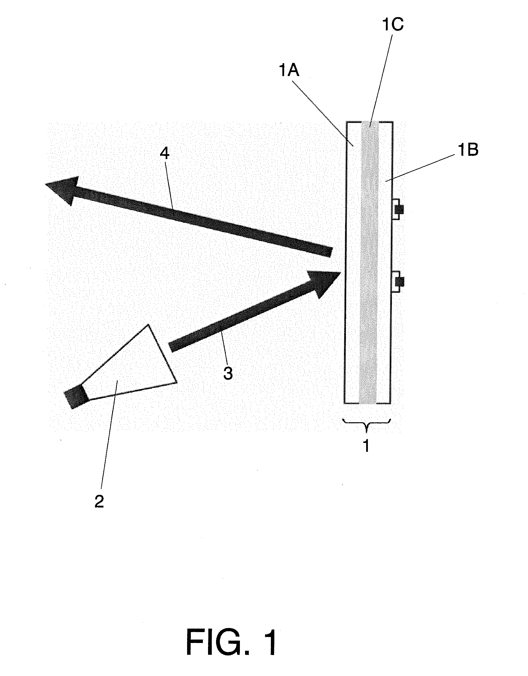
[0100]The reflectarray comprises a plurality of cells integrated in a same substrate or PCB (1) and is externally illuminated by a feeding source (2) as shown in FIG. 1.

[0101]The reflectarray has an input signal (3), which is the illuminating signal at the illuminating or input frequency and an output signal (4) reflected by a reflective surface, being each array cell independently coupled to the feeding source (2) in a star coupling network topology and being each of the cells coupled to its nearest neighbours cells by means of a coupling network.

[0102]Each cell of the reflectarray is an active integrated antenna formed by a passive radiating element connected to an oscillator circuit. The passive radiating circuit is placed on the reflective surface forming a side (1A) of the reflectarray and the oscillator circuit is placed on the reverse side (1...


PUM


Abstract

The reflectarray includes a plurality of cells integrated in a PCB and externally illuminated by an input signal from a feeding source at a frequency fi, and an output signal is reflected, where each cell of the reflectarray is an AIA formed by a passive radiating element connected to an active circuit, which can be either an oscillator, or a push-push oscillator or a SOM, where the passive radiating circuit is placed on a reflective surface forming a side of the reflectarray and the active circuit is placed on the reverse side, the active circuit producing an output signal with a frequency related to the input frequency fi and the oscillation frequency fosc of said active circuit. This phase relationship is determined by an output phase variation, which is controlled by electronic means integrated in the reflectarray system, which allows an output phase variation interval even higher than 180°.

Description

FIELD OF THE INVENTION[0001]The present invention relates to the field of reflective array (reflectarray) antennas, more particularly, deals with a reconfigurable reflectarray based on active integrated antennas (AIAs) and provides the capability of electronically controlling the phase of its reflected wave.STATE OF THE ART[0002]The principle of operation of a reflectarray antenna consists of designing a directive beam by properly synthesizing the reflected wave phase from an array of antenna radiators forming a reflecting surface illuminated by a feed antenna [“The reflectarray antenna”, D. Berry, R. Malech, and W. Kennedy, IEEE Transactions on Antennas and Propagation, vol. 11, no. 6, pp, 645-651, 1963]. In a parabolic reflector topology, a planar wave form is created when the feed antenna is placed in its focal point as all the propagating paths of the illuminating waves reaching the reflecting surface are equal. This does not hold in the case of the planar, or (in general) confo...

Claims


Application Information

Patent Timeline
IPC IPC(8): H01Q3/46H01Q3/42
CPCE02D29/14H01Q3/46H01Q3/42
Inventor GEORGIADIS, APOSTOLOSCOLLADO GARRIDO, ANA
Owner FUNDACIO PRIVADA CENT TECNOLOGIC DE TELECOMUNICACIONS DE CATALUNYA
Why Eureka
Try Eureka