Medical image diagnosis device and medical image processing method
a diagnosis device and image technology, applied in the direction of static indicating devices, instruments, angiography, etc., can solve the problems of taking time and finding an image that a user, and achieve the effect of saving the effort of finding
- Summary
- Abstract
- Description
- Claims
- Application Information
AI Technical Summary
Benefits of technology
Problems solved by technology
Method used
Image

Examples
first embodiment
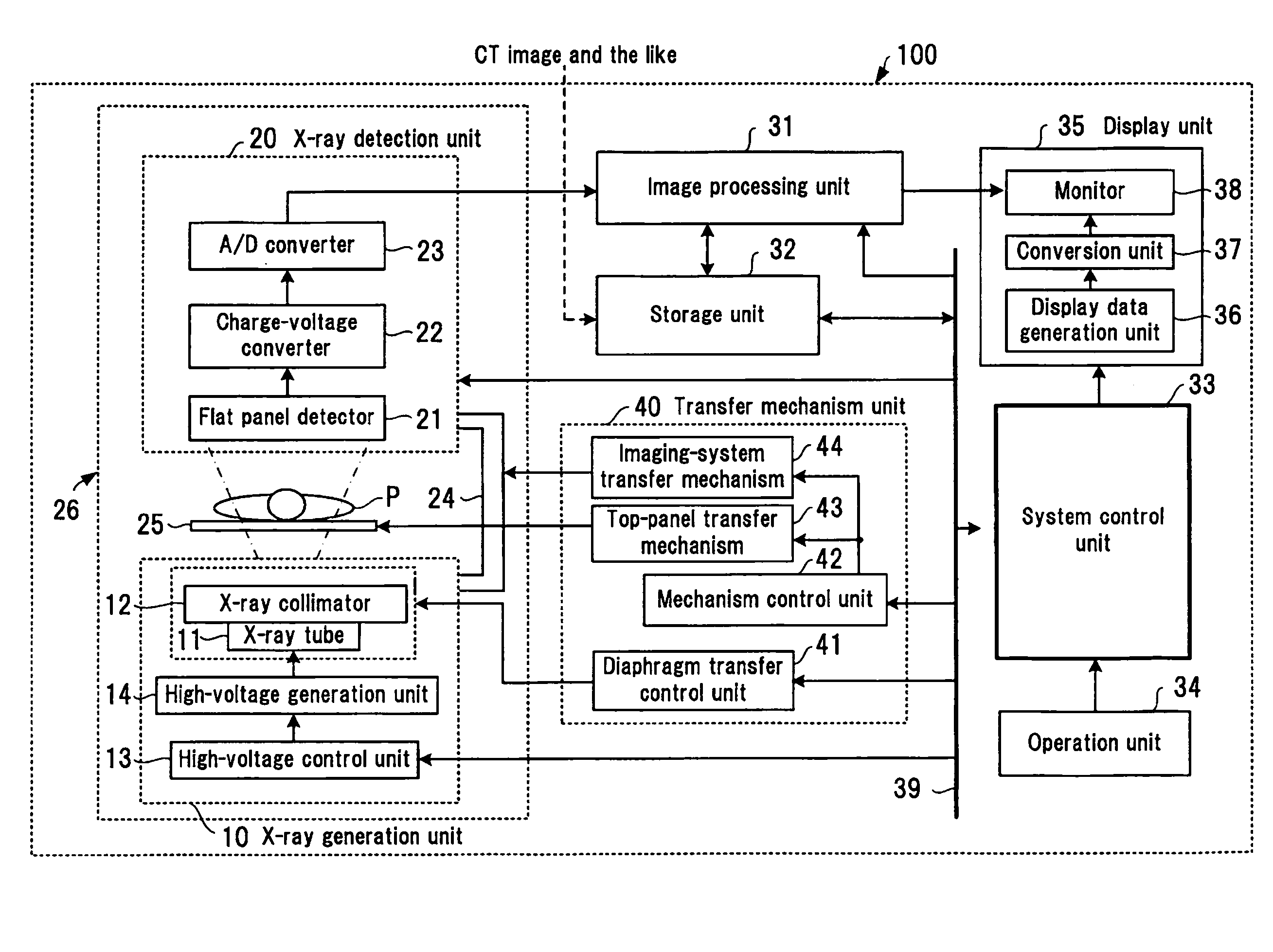
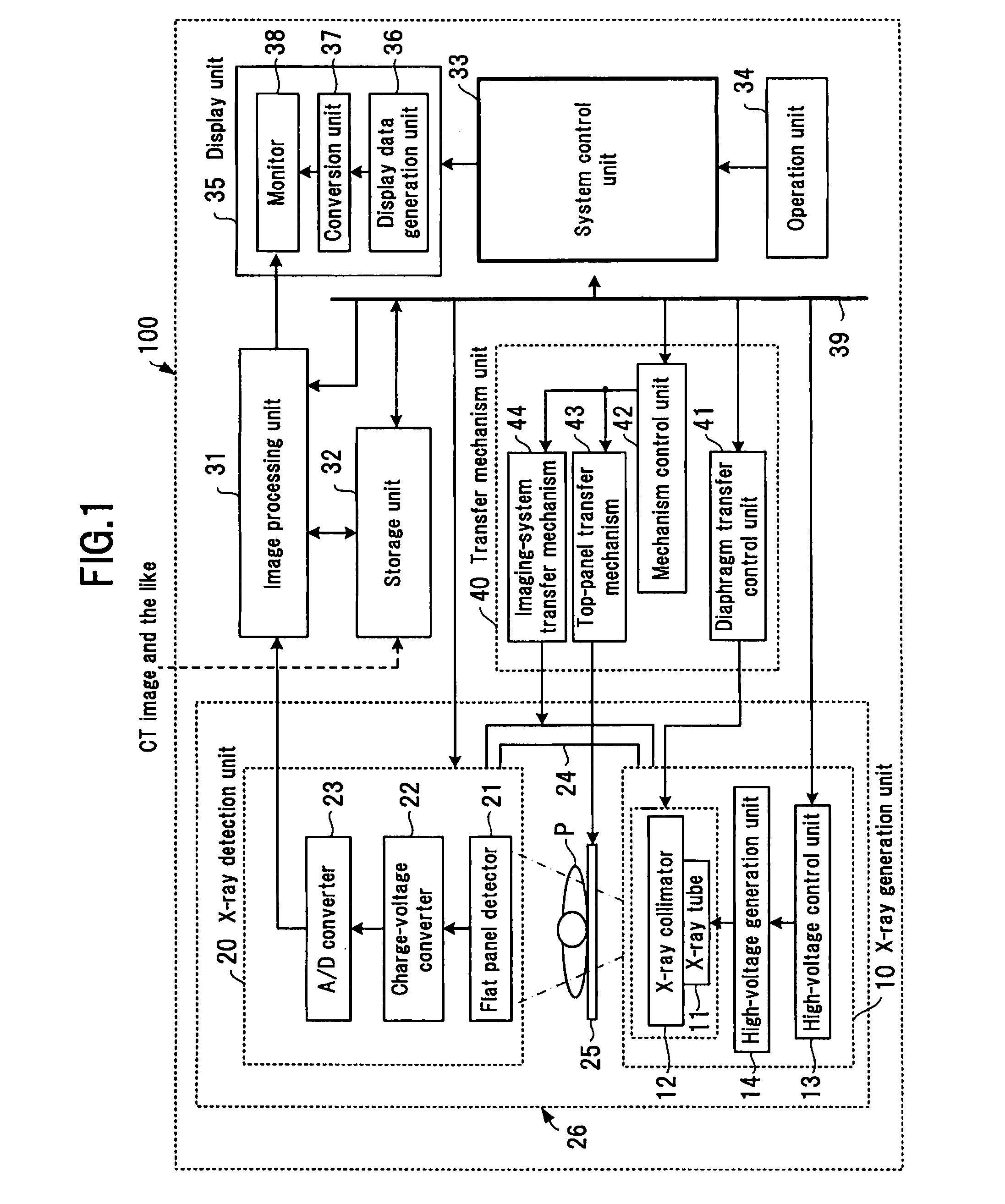
[0023]FIG. 1 is a block diagram showing the configuration of a medical image diagnosis device according to an embodiment. The medical image diagnosis device shown in FIG. 1 is, for example, an X-ray image diagnosis device 100 called an angiography device. The X-ray image diagnosis device 100 includes an X-ray generation unit 10, which generates X-rays for a subject P, and an X-ray detection unit 20, which detects X-rays that have passed through the subject P in a two-dimensional manner and generates X-ray projection data on the basis of the detection results.
[0024]The X-ray generation unit 10 includes an X-ray radiation unit having an X-ray tube 11 and an X-ray collimator 12, a high-voltage control unit 13, and a high-voltage generation unit 14. The X-ray tube 11 is a vacuum tube that generates X-rays; the X-ray tube 11 generates X-rays by using a high voltage to cause electrons emitted from a cathode (filament) to accelerate and strike against a tungsten anode. The high-voltage con...
second embodiment
[0048]A second embodiment of the present invention will be described. According to the second embodiment, on the basis of angular information that supplementary information of image data taken contains, taken images are attached for each angle onto a 3D or 2D model. If there is a plurality of taken images at each angle, the images are displayed so as not to overlap.
[0049]FIG. 6 shows an example in which an imaging range (angular direction) is specified in the 3D human body model 50, images taken at each angle are turned into thumbnails, and a plurality of thumbnail images 55 taken in three directions are attached. FIG. 7 shows an example in which a specific region (the heart, for example) is specified, and, if there are images of the specific region taken from a plurality of angular directions, the images are turned into thumbnails, and a plurality of thumbnail images 56 are attached.
[0050]If there is a plurality of images taken at each angle, the images are displayed so as not to o...
third embodiment
[0053]A third embodiment of the present invention will be described. According to the third embodiment, images taken at each angle are displayed in the form of a matrix. An arbitrary thumbnail image is then selected, identified and displayed.
[0054]FIG. 9(a) shows an example in which a 2D human body model 52 is divided into sections so as to look like a matrix with numbers 1 to 9 attached, and an imaging range (angular direction) is selected by operating a mouse and moving a cursor 53 to a frame of an arbitrary number of the 2D human body model 52. As clicking is performed at a time when the cursor 53 is at an arbitrary position, an angular direction is selected. Image data within the selected imaging range are extracted and turned into thumbnails, and the thumbnail images are disposed on a display screen in chronological order.
[0055]FIG. 9(b) shows an example in which a plurality of pieces of image data corresponding to the No. 6 imaging range exist, and 12 thumbnail images 58 are d...
PUM
 Abstract
Description
Claims
Application Information
 - R&D
- Intellectual Property
- Life Sciences
- Materials
- Tech Scout
- Unparalleled Data Quality
- Higher Quality Content
- 60% Fewer Hallucinations
Browse by: Latest US Patents, China's latest patents, Technical Efficacy Thesaurus, Application Domain, Technology Topic, Popular Technical Reports.
© 2025 PatSnap. All rights reserved.Legal|Privacy policy|Modern Slavery Act Transparency Statement|Sitemap|About US| Contact US: help@patsnap.com