Rocket engine system for realizing high-speed response

Active Publication Date: 2012-07-05
IHI CORP +1
View PDF6 Cites 32 Cited by
  • Summary
  • Abstract
  • Description
  • Claims
  • Application Information

AI Technical Summary

Benefits of technology

[0017]According to the invention, since a turbo pump can be operated in an operation region where the number of rotations of the rotary shaft is maintained constant without depending o

Problems solved by technology

When being converted to a response frequency, the response time of five seconds is 0.2 (Hz), and it is not possible to satisfy high-speed respon

Method used


Image

  • Rocket engine system for realizing high-speed response
  • Rocket engine system for realizing high-speed response
  • Rocket engine system for realizing high-speed response

Examples


Embodiment Construction

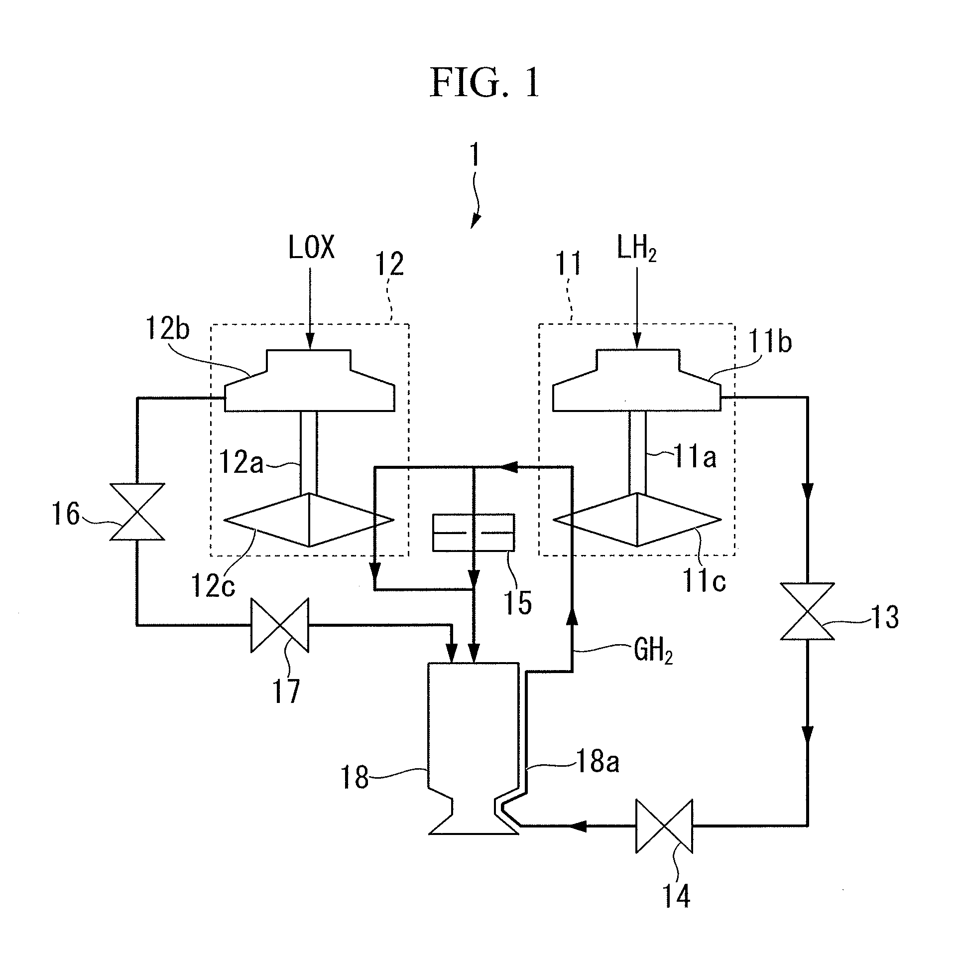
[0028]Hereinafter, an embodiment of the invention will be described with reference to the drawings. The following description will be provided as to an expander cycle engine, in which liquid hydrogen (LH2) is used as fuel and liquid oxygen (LOX) is used as an oxidizer, as a rocket engine including a turbo pump according to the invention.

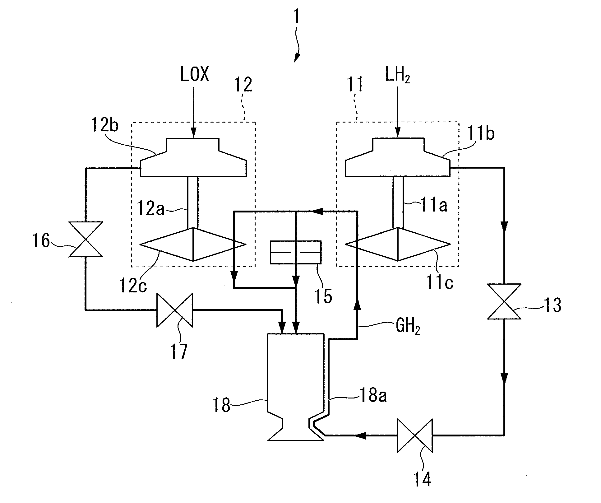
[0029]FIG. 1 is a schematic configuration diagram of a rocket engine 1 of this embodiment. As shown in FIG. 1, the rocket engine 1 of this embodiment schematically includes a fuel turbo pump 11, an oxidizer turbo pump 12, a fuel-side thrust control valve 13, a fuel-side main valve 14, a bypass orifice 15, an oxidizer-side thrust control valve 16, an oxidizer-side main valve 17, and a combustor 18.

[0030]The fuel turbo pump 11 is a centrifugal turbo pump in which a pump impeller 11b is connected to one end of a rotary shaft 11a rotatably supported in a body casing, and a turbine 11c is connected to the other end of the rotary shaft 11a. The fuel turbo ...


PUM


Abstract

Disclosed is a turbo pump in which a pump impeller is connected to one end of a rotary shaft and a turbine is connected to the other end of the rotary shaft. The turbo pump is designed such that an equivalent region, between a turbine efficiency curve obtained on the basis of a conditional expression where the number of rotations of the rotary shaft is maintained constant regardless of a pump flow rate and a turbine efficiency curve of an actual machine, becomes an operation region.

Description

TECHNICAL FIELD[0001]The present invention relates to a turbo pump and a rocket engine system for realizing high-speed response.[0002]Priority is claimed on Japanese Patent Application No. 2009-207480, filed Sep. 8, 2009, the content of which is incorporated herein by reference.BACKGROUND ART[0003]In recent years, as a liquid-fueled engine which is mounted in an aerospace vehicle, such as a rocket, the use of a turbo pump-type rocket engine in which a propellant (for example, liquid hydrogen as fuel and liquid oxygen as an oxidizer) is pumped to a combustor by a turbo pump to obtain a large propulsive force has become mainstream. For example, Patent Document 1 describes an expander cycle engine, as one form of a turbo pump-type rocket engine, in which liquid hydrogen pumped from a fuel turbo pump is used for regenerative cooling of a combustor and gasified, hydrogen gas is used for driving the fuel turbo pump and the oxidizer turbo pump and then introduced to the combustor, and liqu...

Claims


Application Information

Patent Timeline
IPC IPC(8): F02K9/46F02K9/64F01D15/08
CPCF04D13/028F02K9/46F05D2270/024F04D13/04
Inventor MORI, HATSUONARUO, YOSHIHIROTOKUDOME, SHINICHIROYAGISHITA, TSUYOSHIYAMAMOTO, TAKAYUKIINATANI, YOSHIFUMI
Owner IHI CORP
Why Eureka
Try Eureka