Method and Diagnostic Device for Diagnosing a Heatable Exhaust Gas Sensor of an Internal Combustion Engine

Active Publication Date: 2012-07-05
ROBERT BOSCH GMBH
View PDF3 Cites 26 Cited by
  • Summary
  • Abstract
  • Description
  • Claims
  • Application Information

AI Technical Summary

Benefits of technology

[0008]The exemplary embodiments and/or exemplary methods of the present invention are based on the object of providing a method for diagnosing an exhaust gas sensor of an internal combustion engine, which permits reliable and accurate diagnosis o

Problems solved by technology

A system error is recognized, for example, if the variables detected with the aid of different sensors contradict one another.
Since there are complex interactions between various components of the internal combustion engine during operation of the internal combustion engine, however, a sufficiently secure and reliable diagnosis of an individual lambda sensor is not possible.
For example, if an electrical error is recognized, it typically cannot be reliably established whether the error is based on a defect of the lambda sensor or whether the control and/or regulating unit, in particular an analysis circuit for the sensor signals of the lambda sensor, is defective.
In addition, in many cases sys

Method used


Image

  • Method and Diagnostic Device for Diagnosing a Heatable Exhaust Gas Sensor of an Internal Combustion Engine
  • Method and Diagnostic Device for Diagnosing a Heatable Exhaust Gas Sensor of an Internal Combustion Engine
  • Method and Diagnostic Device for Diagnosing a Heatable Exhaust Gas Sensor of an Internal Combustion Engine

Examples


Embodiment Construction

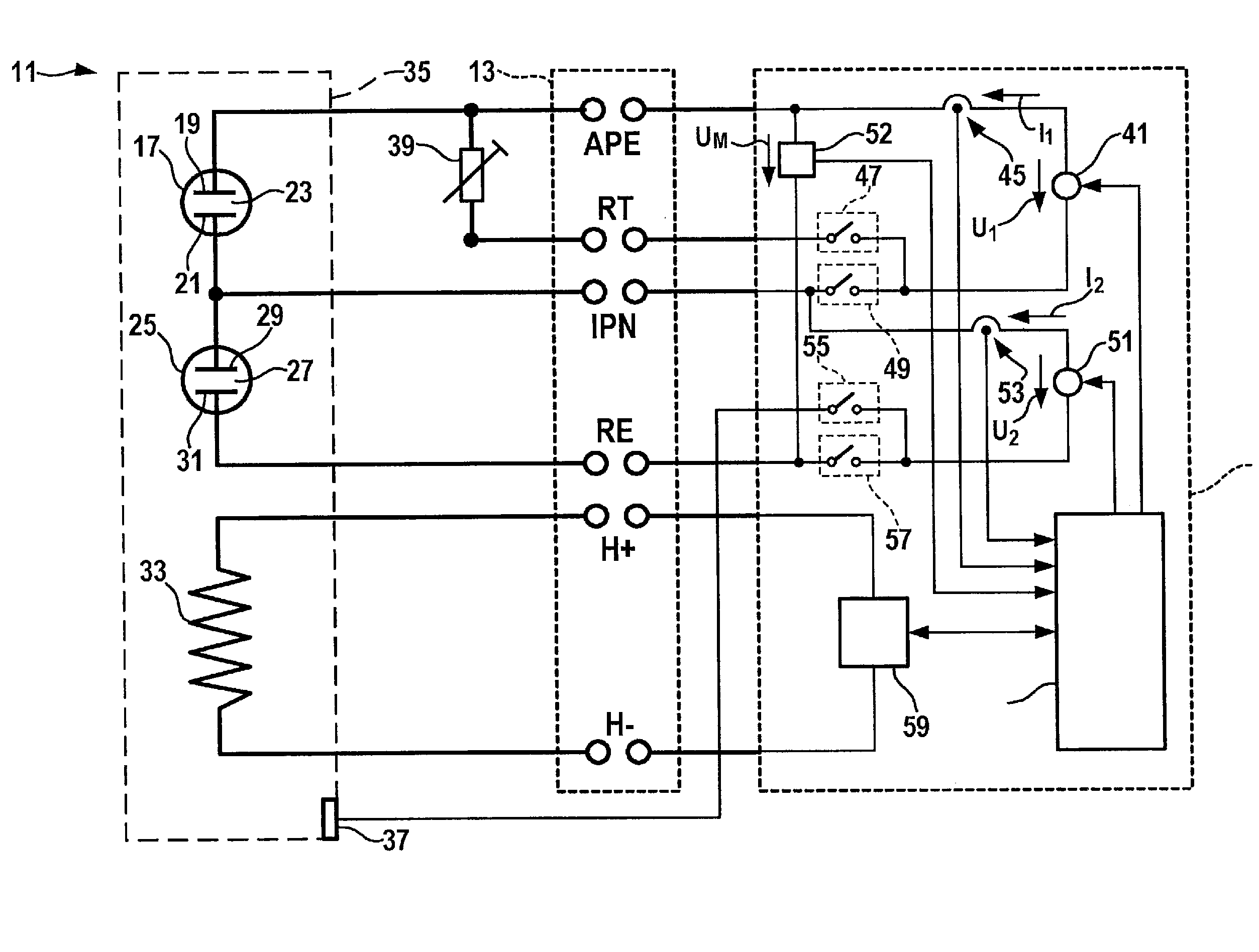
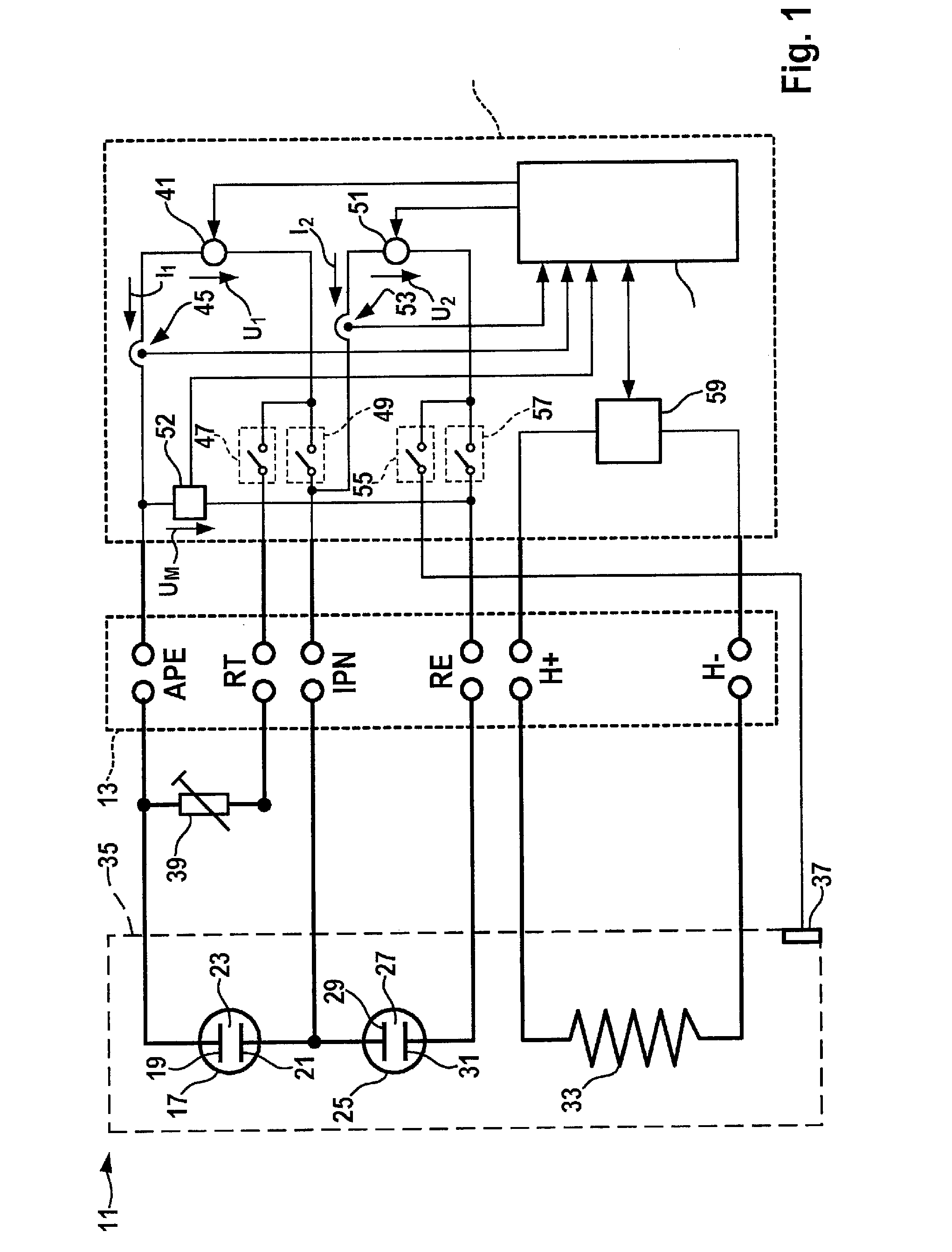
[0036]The schematic view of FIG. 1 shows a dual-cell broadband lambda sensor 11, which is connected to a diagnostic device 15 via an electrical connection in the form of a plug connector 13. Lambda sensor 11 is part of an exhaust gas system of an internal combustion engine (not shown). It may be situated upstream or downstream from an exhaust gas catalytic converter in an exhaust pipe of the exhaust gas system in the flow direction, for example. Lambda sensor 11 may also be temporarily removed from the internal combustion engine for the purpose of a diagnosis, however. It is also conceivable that lambda sensor 11 is provided for the initial installation in the internal combustion engine and is connected to diagnostic device 15 for an initial function test. The initial function test may also be carried out when lambda sensor 11 is already installed.

[0037]Lambda sensor 11 has a pump cell 17. Pump cell 17 includes an outer pump electrode 19, which is connected to a terminal of plug con...


PUM


Abstract

A method is described for diagnosing a heatable exhaust gas sensor of an internal combustion engine, in which a predefined chronologically varying or constant voltage or a predefined chronologically varying or constant current is generated with the aid of a voltage source, the voltage or the current is applied to terminals of the exhaust gas sensor, a current or applied voltage, which flows through the voltage source when the voltage or the current is applied, is detected, and the current or the voltage is analyzed to diagnose the exhaust gas sensor. To diagnose the exhaust gas sensor, which permits a reliable and accurate diagnosis of the exhaust gas sensor and allows a statement about the type of a possibly existing error on the exhaust gas sensor, the method is executed independently of a control and/or regulating unit of the internal combustion engine, an operating temperature of the exhaust gas sensor being regulated to a predefined temperature value with the aid of a regulating element, which is separate from the control and/or regulating unit.

Description

FIELD OF THE INVENTION[0001]The present invention relates to a method for diagnosing a heatable exhaust gas sensor of an internal combustion engine and a diagnostic device.BACKGROUND INFORMATION[0002]Equipping internal combustion engines, in particular internal combustion engines for motor vehicles, with one or more exhaust gas sensors is generally known. The exhaust gas sensors are typically connected to a control and / or regulating unit of the internal combustion engine, so that the control and / or regulating unit may detect information about the composition of exhaust gases exiting from combustion chambers of the internal combustion engine. Typically at least one lambda sensor, which may be used to detect an oxygen concentration in the exhaust gas, is provided as an exhaust gas sensor in an internal combustion engine. This allows a conclusion to be drawn about an air / fuel ratio in the combustion chamber, so that the internal combustion engine may be regulated in such a way, for exa...

Claims


Application Information

Patent Timeline
IPC IPC(8): G01N33/00
CPCF02D41/1494G01N27/4175F02D41/266F02D41/1495
Inventor VERDIER, CYRILKLEIN, STEFANLEMKE, GERHARDGLASHOFF, KARSTENBRIDA, PETERMEIER, FRANKSEILER, THOMAS
Owner ROBERT BOSCH GMBH
Why Eureka
Try Eureka