Oil field water recycling system and method

a technology of oil field and water recycling system, applied in the direction of multi-stage water/sewage treatment, other chemical processes, separation processes, etc., can solve the problems of limiting efforts to create a cost effective treatment system that can treat or recycle the spectrum of possible produced water streams, and the production of water is typically contaminated

Inactive Publication Date: 2012-07-05
EVANS THOMAS S
View PDF5 Cites 30 Cited by
  • Summary
  • Abstract
  • Description
  • Claims
  • Application Information

AI Technical Summary

Benefits of technology

[0004]The disclosure describes a novel approach for treating water, such as oilfield production waste. The disclosure describes novel methods for chemically treating contaminated water, such as chemical processes for softening water, demulsifying hydrocarbons, destroying a sequestering effect on divalent cations, destroying any detectable amount or over 99% of aerobic and anaerobic bacteria, and breaking long chain polymers. The disclosure further describes novel methods for clarifying contaminated water to remove suspended solids.

Problems solved by technology

Produced water is typically contaminated with significant concentrations of chemicals and substances requiring that it be disposed of or treated before it can be reused or discharged to the environment.
Because of the very wide range of contaminant species as well as the different quality of produced water from different sources, efforts to create a cost effective treatment system that can treat or recycle the spectrum of possible produced water streams have been limited.

Method used


Image

  • Oil field water recycling system and method
  • Oil field water recycling system and method
  • Oil field water recycling system and method

Examples


examples

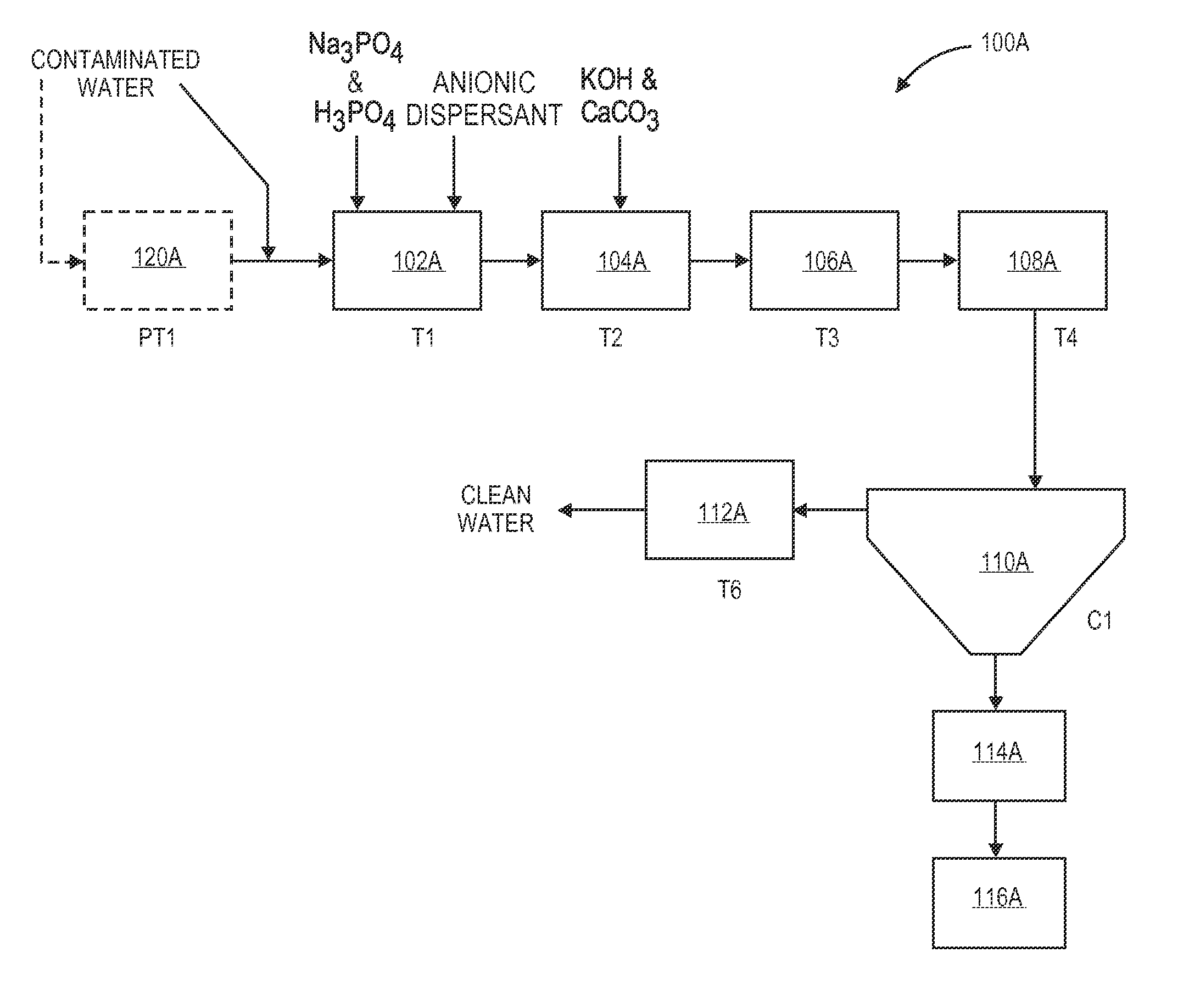
[0156]In one example, contaminated water was ran through a system 100A according to FIG. 1A. The system 100A was ran utilizing the following compounds at the listed amounts in the appropriate tanks as described above:

Tightly emulsified clarifier100 ppmPhosphoric acid and sodium phosphate200 ppmPotassium Hydroxide (45%)0.25%Calcium hydroxide (5% solution)0.25%Coagulant 60 ppmFlocculant (0.20% solution)0.25%Hydrochloric acid0.20%

Measurements were taken of the contaminated water fed into system 100A. Measurements were taken of the water after treatment with system 100A. Table 1 below lists the measurements from the contaminated water and from the water after treatment with system 100A.

TABLE 1ContaminatedAfterGeneral ParametersWaterTreatmentpH6.47.5Electrical Conductivity2640028400Total Dissolved Solids (180)1970019800Solids, Total Dissolved (Calc)1620020300Total Suspended Solids10828TurbiditySulfate Reducing Bacteria>100,0001-10Alkalinity, Total (As CaC03)847857Hardness, Calcium / Magnes...


PUM

PropertyMeasurementUnit
diameteraaaaaaaaaa
weight ratioaaaaaaaaaa
temperaturesaaaaaaaaaa

Abstract

A system is used for treating contaminated water, that may include some amount of polyacrylamides, emulsified hydrocarbons, and sequestered divalent cations. The system includes at least one pre-treatment tank for initial processing of the contaminated water. Thereafter, the water may be fed to at least one chemical treatment tank fluidically connected to the pre-treatment tank. This treatment tank includes a chemical injection system connected to an interior thereof for introducing a variety break operations, coagulant addition operations, and/or flocculent addition operations. At least one clarifier is fluidically connected to the at least one chemical treatment tank, and includes a mechanical contaminant removal system. A filter skid is fluidically connected to the at least one clarifier, and includes a plurality of filter cartridges.

Description

CROSS-REFERENCE TO RELATED APPLICATIONS[0001]This application claims priority to and the benefit of U.S. Provisional Patent Application Ser. No. 61 / 454,213, filed Mar. 18, 2011; and is a continuation-in-part of U.S. patent application Ser. No. 12 / 792,164, filed Jun. 2, 2010, which claims priority to and the benefit of U.S. Provisional Patent Application Ser. No. 61 / 184,169, filed Jun. 4, 2009; all of which are entitled, “Oil Field Water Recycling System and Method,” the disclosures of which are hereby incorporated by reference herein in their entireties.INTRODUCTION[0002]Water, especially in the western United States and other arid regions, is a valuable resource. Many oil and natural gas production operations generate, in addition to the desired hydrocarbon products, large quantities of waste water, referred to as “produced water”. Produced water is typically contaminated with significant concentrations of chemicals and substances requiring that it be disposed of or treated before ...

Claims


Application Information

Patent Timeline
Patent Type & Authority Applications(United States)
IPC IPC(8): B01D36/04C02F9/08
CPCC02F1/5236C02F1/56C02F1/66C02F1/72C02F2303/04C02F2101/30C02F2101/32C02F2101/36C02F2103/10C02F5/083
Inventor EVANS, THOMAS S.
Owner EVANS THOMAS S
Why Eureka
Try Eureka