Eureka AIR delivers breakthrough ideas for toughest innovation challenges, trusted by R&D personnel around the world.

Method and system for extracting a substance by means of Anti-sublimation and melting

Inactive Publication Date: 2012-07-12
ASSOC POUR LA RECH & LE DEV DES METHODES & PROCESSUS IND (ARMINES)
View PDF4 Cites 8 Cited by
  • Summary
  • Abstract
  • Description
  • Claims
  • Application Information

AI Technical Summary

Benefits of technology

[0041]The inventors have established that subdividing an extraction method temporally into four successive functional steps means that the heat-exchange areas employed and the flow rates of the refrigerant fluids associated either with frosting or else with defrosting can be managed more effectively.
[0052]Thus, the invention can be used to significantly reduce the variations in the three distinct types of flow while extracting a substance. In other words, the invention can be used to significantly improve the distribution of the flows employed throughout the method of extracting the desired substance.
[0072]Carrying out this evacuating sub-step advantageously means that undesirable residual gases present in the chamber can be evacuated at the end of the frosting step. Thus, at the end of the defrosting step, a chamber may contain a very pure gas, i.e. a gas with a very high concentration of the substance to be extracted. In this manner, during the recovery step it is possible to recover an extracted substance of very high purity, both in the liquid form and in the form of residual gases.

Problems solved by technology

However, that device exhibits undesirable effects, such as significant variations in the flow rate of the refrigerant fluids (or coolant and heat-transfer fluids) flowing in the freezing system, as well as undesirable energy losses.
Those undesirable effects are magnified when, as is usual, the extraction systems are large in size,
As an example, systems for extracting CO2 from the fumes from electricity production units using coal are very bulky.

Method used


Image

  • Method and system for extracting a substance by means of Anti-sublimation and melting
  • Method and system for extracting a substance by means of Anti-sublimation and melting
  • Method and system for extracting a substance by means of Anti-sublimation and melting

Examples


Embodiment Construction

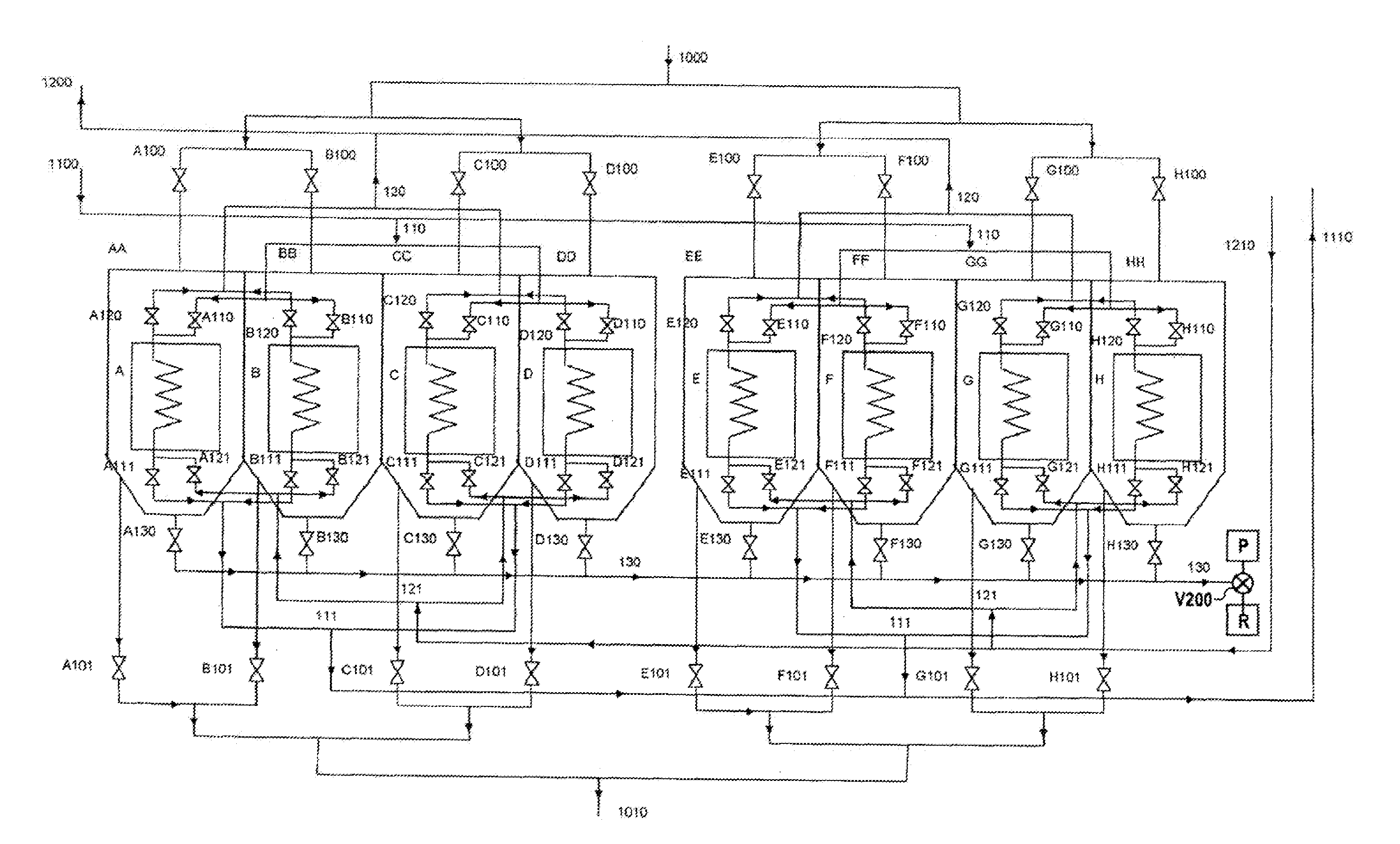
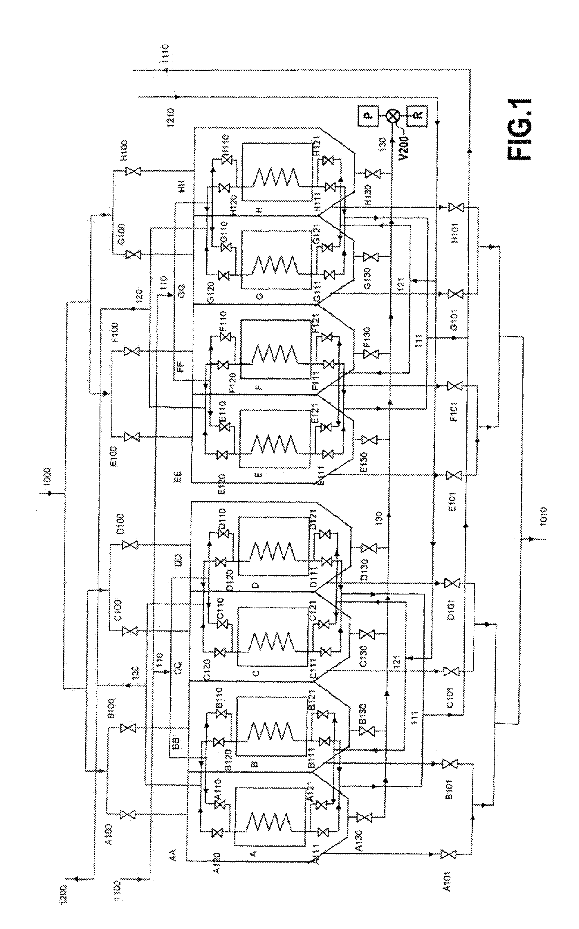
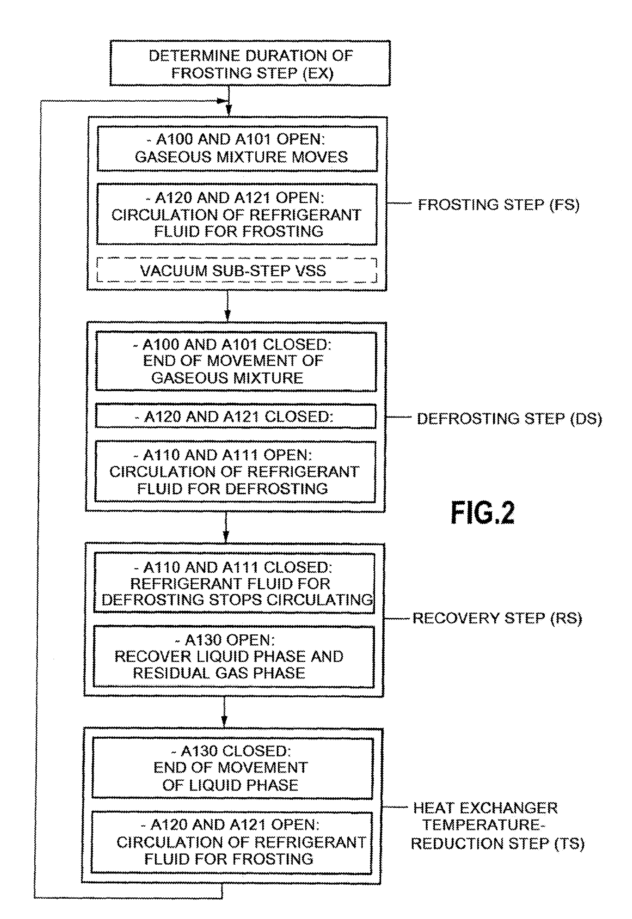
[0134]The present invention provides a system for extracting a substance present in a mixture of process gas or fumes, by bringing about anti-sublimation of that substance on the solid surface of a plurality of freezing heat-exchangers.

[0135]To this end, anti-sublimation of the substance to be extracted is carried out at a temperature and at a pressure lower than that defined by the triple point of the substance under consideration.

[0136]The extraction system of the invention comprises 2N heat-exchangers, N being an integer greater than or equal to three.

[0137]FIG. 1 represents an example of an extraction system of the invention. In this example, the extraction system comprises eight distinct heat-exchangers, such that N is equal to 4.

[0138]The eight heat-exchangers have been shown in FIG. 1 (denoted A, B, C, D, E, F, G, and H).

[0139]The extraction system of FIG. 1 also comprises eight chambers AA, BB, CC, DD, EE, FF, GG, and HH in which the respective freezing heat-exchangers A, B,...


PUM

PropertyMeasurementUnit
Forceaaaaaaaaaa
Temperatureaaaaaaaaaa
Pressure dropaaaaaaaaaa

Abstract

The invention provides a method and a system for extracting a substance comprised in a gaseous mixture, the extraction being carried out in a cyclic manner in 2N chambers (AA, BB, CC, DD), each provided with a heat-exchanger (A, B, C, D), N being an integer greater than or equal to 3. Each chamber carries out a cycle comprising the following four steps in succession: a frosting step, a defrosting step, a step of recovering the liquid phase and the residual gas phase, and a temperature-reduction step of reducing the temperature of the heat-exchanger. Further, sequencing the passage from one step to another in each of the chambers is such that the number of chambers carrying out the frosting step and also the total number of chambers carrying out the defrosting, recovery, and temperature-reduction steps are both equal to N.

Description

BACKGROUND OF THE INVENTION[0001]The invention relates to the field of separating gases and is targeted at optimizing a method of extracting one or more substances included in a gaseous mixture by anti-sublimation then melting.[0002]The anti-sublimation process corresponds to the direct passage of one or more gases from the gas phase into the solid phase (the reverse-of the sublimation process).[0003]More particularly, the invention relates to optimizing the management of the processes of frosting (or anti-sublimation) and defrosting comprising sublimation then melting on a plurality of heat-exchangers; implementing said processes requires managing the timing of distinct elementary operations.[0004]In order to obtain anti-sublimation of a substance on a heat-exchanger, it is necessary for the substance to be at a partial pressure that is lower than that defined by its triple point, and also for the temperature of the surface of the heat-exchanger to be lower than that of the triple ...

Claims


Application Information

Patent Timeline
IPC IPC(8): F25J3/08
CPCB01D7/02B01D53/002B01D53/48B01D53/62B01D53/64Y02C10/04B01D2257/504B01D2257/602B01D2258/0283F23J2900/15061B01D2257/302Y02C20/40Y02P70/10
Inventor CLODIC, DENISYOUNES, MOURADRIACHI, YOUSSEFFBOU LAWZ KSAYER, ELIAS
Owner ASSOC POUR LA RECH & LE DEV DES METHODES & PROCESSUS IND (ARMINES)
Why Eureka
Eureka Blog
Learn More