Concentrating tracking solar energy collector

Inactive Publication Date: 2012-07-12
SNIPES BRADFORD JOEL
View PDF0 Cites 19 Cited by
  • Summary
  • Abstract
  • Description
  • Claims
  • Application Information

AI Technical Summary

Benefits of technology

[0038]Both of the embodiments of the present invention are supported at the top of a pedestal support column by three hydraulic cylinders. The arrangement of the three hydraulic cylinders is such that the collector may be aimed at the sun wherever the sun is in the sky. Solar tracking of this collector is easily automated. The support pedestal comprises a vertically mounted support column which is anchored at its bottom end to a suitable foundation. Three collector support arms extend horizontally outward from the top of the vertical support column at 120 degree equal intervals.
[0039]A

Problems solved by technology

However, none of them are economically competitive with conventional utilities which burn fossil fuels for electrical energy production.
Both of these designs are relatively inefficient when compared to the present invention.
This low efficiency necessitates even larger areas of solar collection per unit of energy produced.
Also, the cost per unit of area projected to the sun is high because very expensive materials are used.
A large part of the thermal energy collected is lost by radiation and convection from the sheet before it reaches the fluid flowing through the tubes.
Again, the cost per unit area projected to the sun is high because expensive materials are used.
These f

Method used


Image

  • Concentrating tracking solar energy collector
  • Concentrating tracking solar energy collector
  • Concentrating tracking solar energy collector

Examples


Embodiment Construction

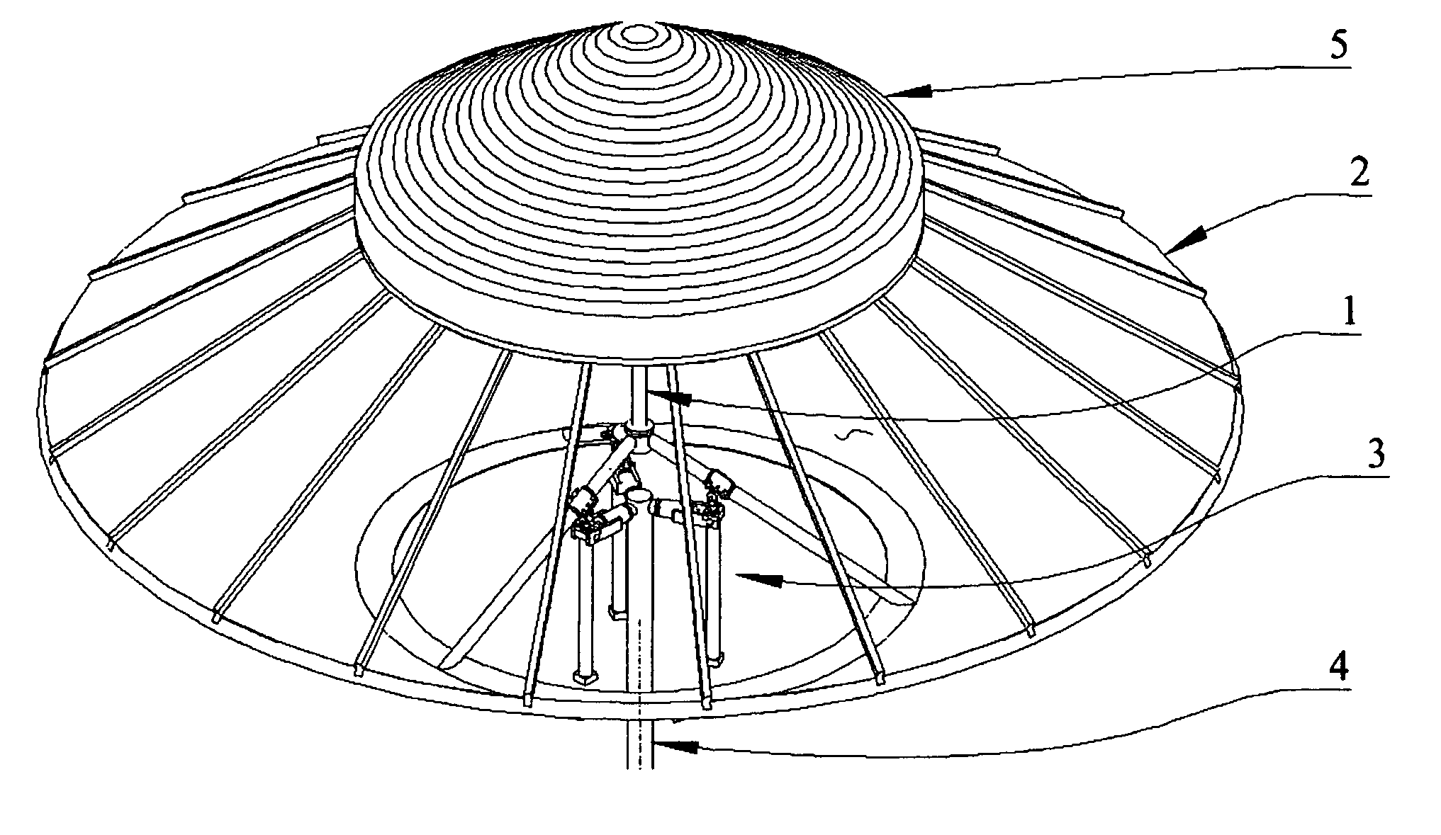
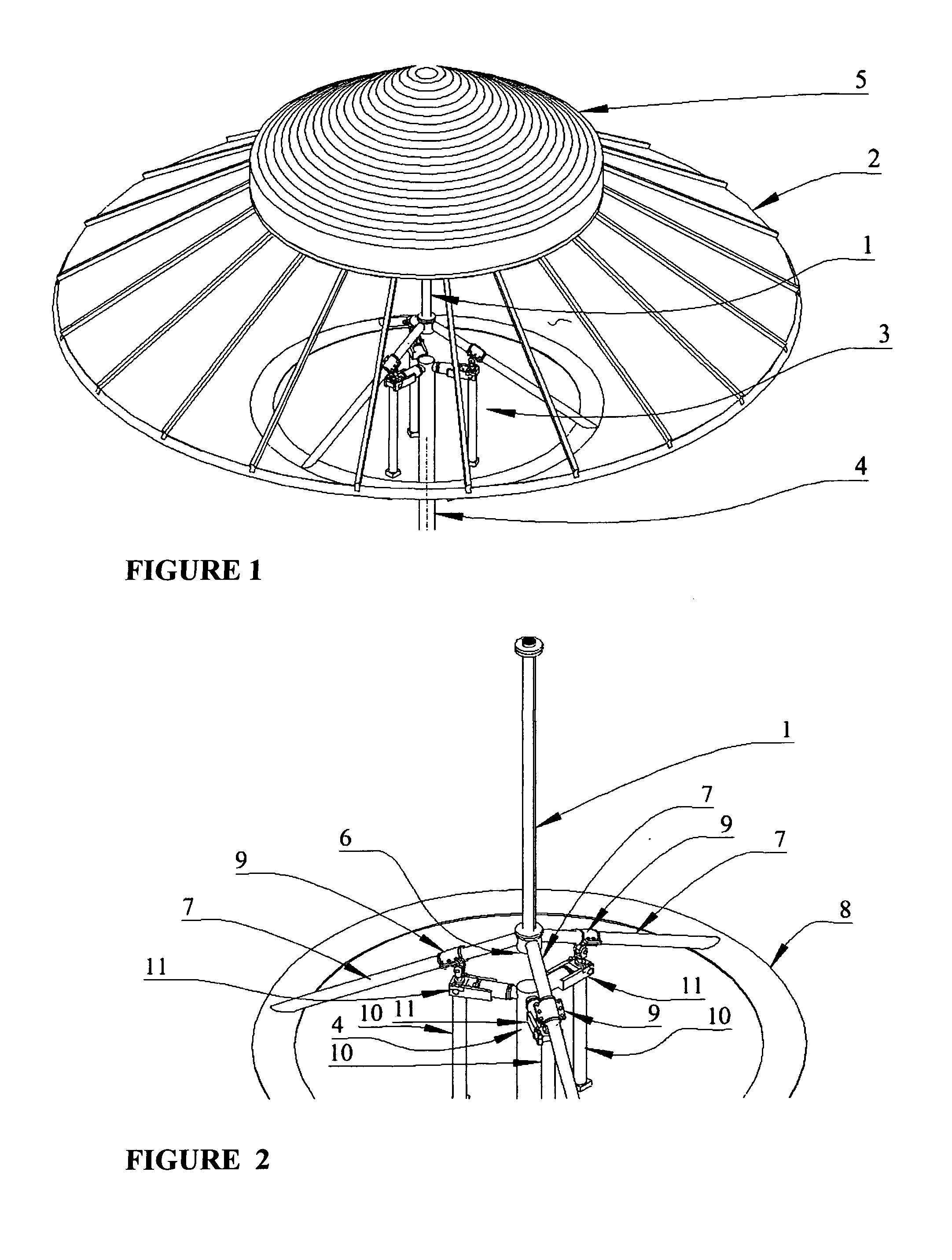
[0061]The device includes a solar collector moveably mounted on a support pedestal. The support pedestal may be attached to a concrete foundation on the ground. Other mounting configurations may be utilized.

[0062]An inverted truncated conical reflecting surface concentrates and focuses about 90%-95% of the incident solar radiation onto an absorber pipe assembly.

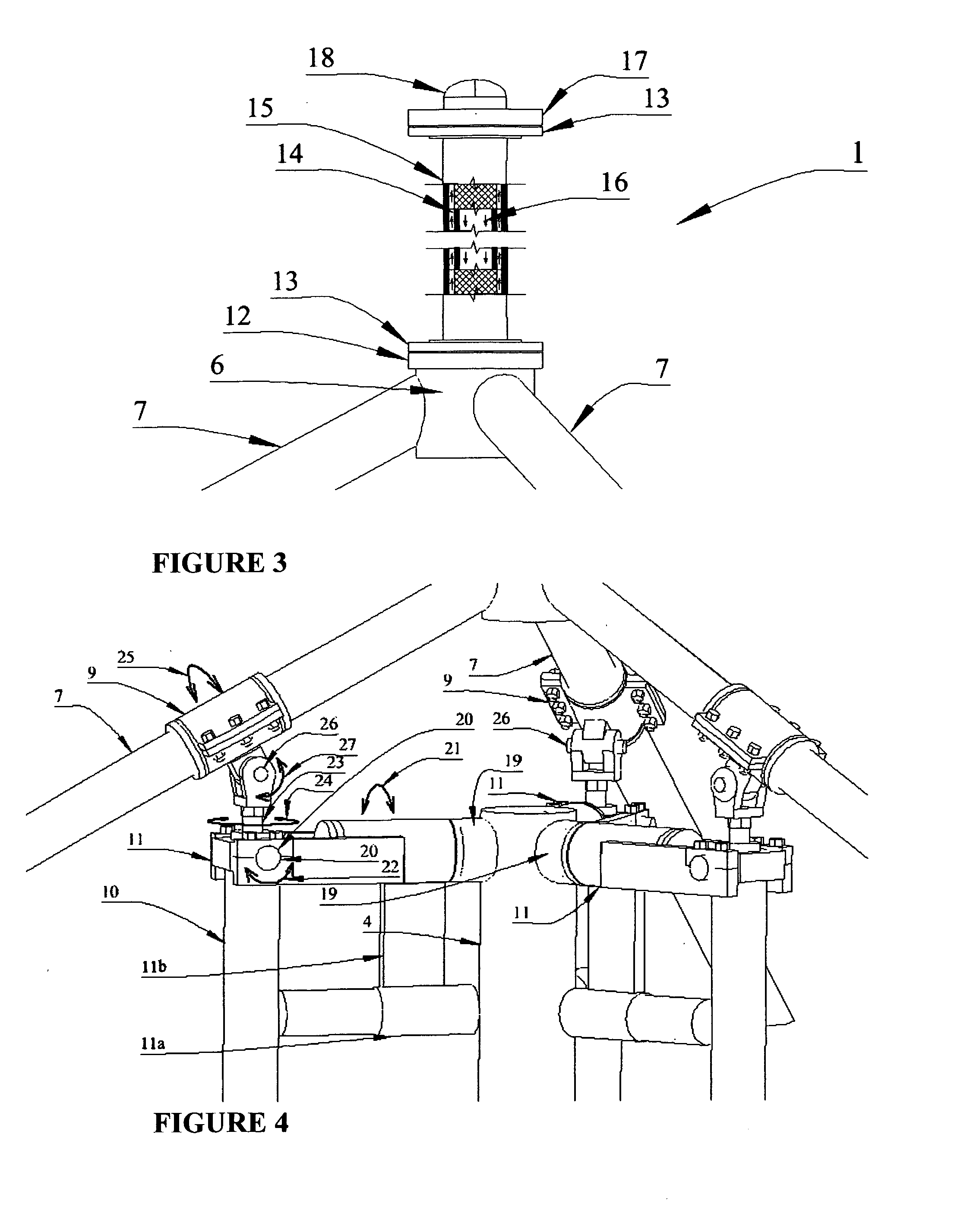
[0063]In one embodiment, the absorber pipe assembly consists of a black absorber pipe placed coaxially within a clear glass process pipe. This clear glass process pipe is highly transmissive to solar radiation and also has the capability of containing a fluid under pressures up to 100 psig and temperatures over 400° F.

[0064]In operation a heat transfer fluid like Propylene Glycol is pumped through the annulus between the black pipe and the clear glass pipe The heat is transferred away from the absorber pipe assembly by means of the fluid.

[0065]About 90% of the incoming radiant solar energy is concentrated and focused onto the...


PUM


Abstract

A Conical reflecting, concentrating, two-axis tracking solar energy collector is disclosed.
An inverted multi-segmented conical reflecting surface concentrates and focuses solar energy at very high concentrations onto a very thermodynamically efficient receiver tube or absorber pipe assembly.
The receiver tube consists of a cylindrical array of HCPV solar cells mounted onto a polygonal extruded Aluminum tube. These HCPV solar cells are 36% efficient and can receive solar concentrations as high as 1000 SUNS. A heat transfer fluid is pumped through the receiver tube in contact with the interior surface of the Aluminum tube to remove the heat from the HCPV solar cells. In cooling the HCPV cells, the heat transfer fluid is heated. The resulting thermal energy, ⅔ of the available solar energy, can be utilized for ammonia absorption air conditioning and home heating, about ⅔-¾ of a home's energy requirement.
The absorber pipe assembly encloses a black surfaced absorber pipe within a larger diameter transparent glass pipe and a heat transfer fluid is pumped through the annulus in direct contact with the black absorbing surface. A very efficient transfer of heat is effected.
This conical concentrator and receiver combination is caused to track the by three hydraulic cylinders.
The concentrating solar energy collector disclose is intended to and is capable of economically providing for all of the energy needs of a home or building.

Description

BACKGROUND TO THE DISCLOSURE[0001]1. Field of Use[0002]This device relates to the conversion of solar radiation into both electrical and thermal energy.[0003]The objective of this device is to provide for all of the energy requirements of a home, building or community.[0004]2. Prior Art[0005]Relatively low energy densities of available solar radiation at the Earth's surface dictate the use of large areas of solar collection per unit of energy produced.[0006]Many solar collectors available today are proven. However, none of them are economically competitive with conventional utilities which burn fossil fuels for electrical energy production. The solar energy industry has been competing with the artificially low cost of fossil fuels.[0007]Solar collectors which presently predominate the solar home energy market include flat plate thermal energy collectors and flat non-concentrating photovoltaic solar cell arrays.[0008]Both of these designs are relatively inefficient when compared to t...

Claims


Application Information

Patent Timeline
IPC IPC(8): H01L31/058H01L31/052H01L31/0232
CPCY02B10/10H01L31/0547Y02B10/70F24J2/07F24J2/15F24J2/38F24J2/5431H01L31/0521F24J2002/5441F24J2002/5482Y02E10/52Y02E10/41Y02E10/47H02S20/00Y02B10/20F24S20/20F24S23/75F24S30/48F24S50/20F24S2030/115F24S2030/15H02S20/32Y02E10/40
Inventor SNIPES, BRADFORD JOEL
Owner SNIPES BRADFORD JOEL
Why Eureka
Try Eureka