Remote displacement sensor, including an optical strain gauge, an assembly and system therewith

Active Publication Date: 2012-07-12
ILLINOIS TOOL WORKS INC
View PDF3 Cites 37 Cited by
  • Summary
  • Abstract
  • Description
  • Claims
  • Application Information

AI Technical Summary

Benefits of technology

[0007]It is therefore an object of the present disclosure to provide a remote displacement sensor, such as, but n

Problems solved by technology

While well-adapted to their intended purposes, clip-on extenso

Method used


Image

  • Remote displacement sensor, including an optical strain gauge, an assembly and system therewith
  • Remote displacement sensor, including an optical strain gauge, an assembly and system therewith
  • Remote displacement sensor, including an optical strain gauge, an assembly and system therewith

Examples


Example

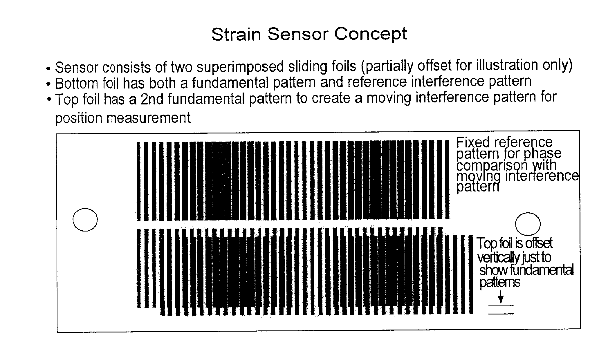
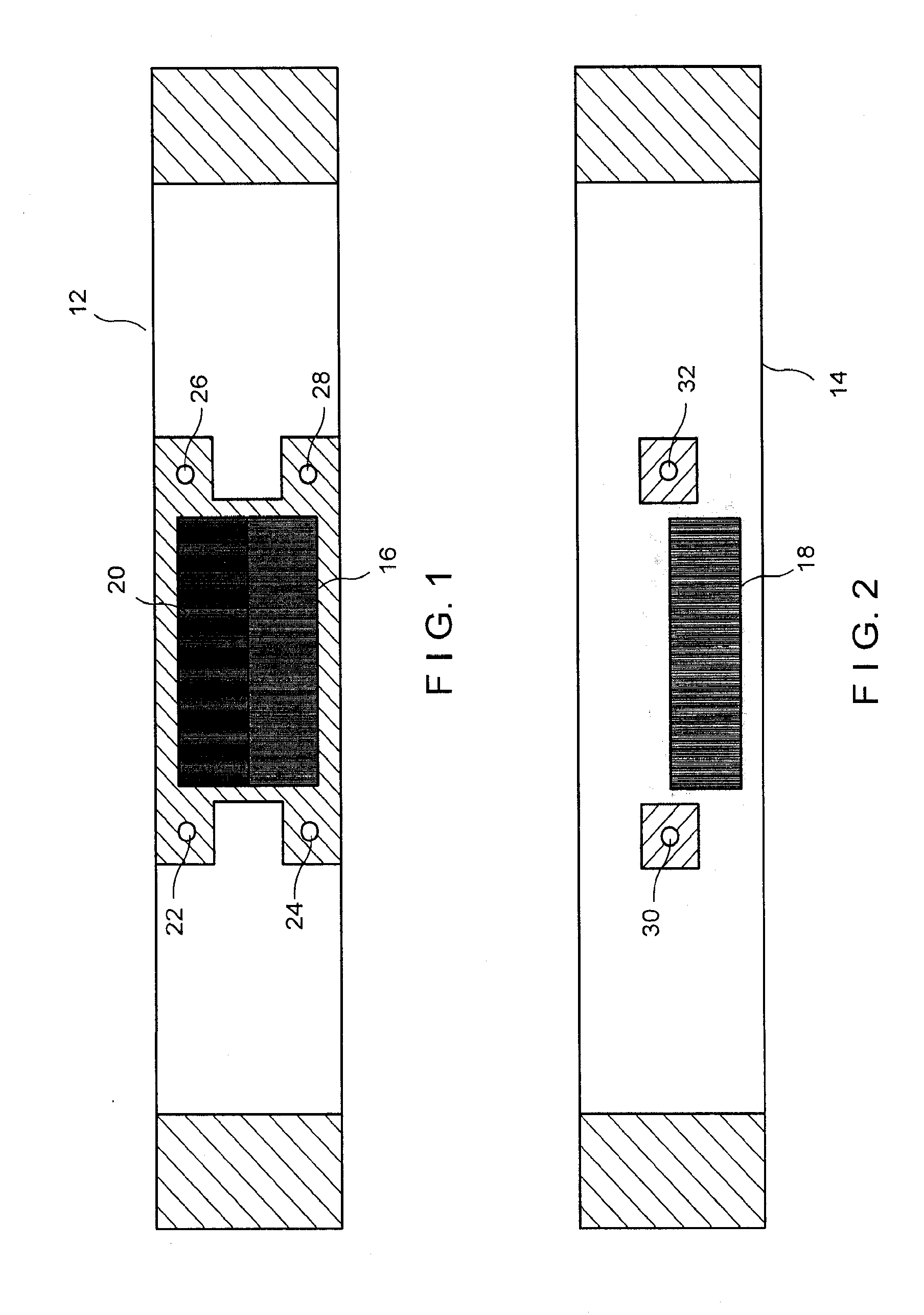
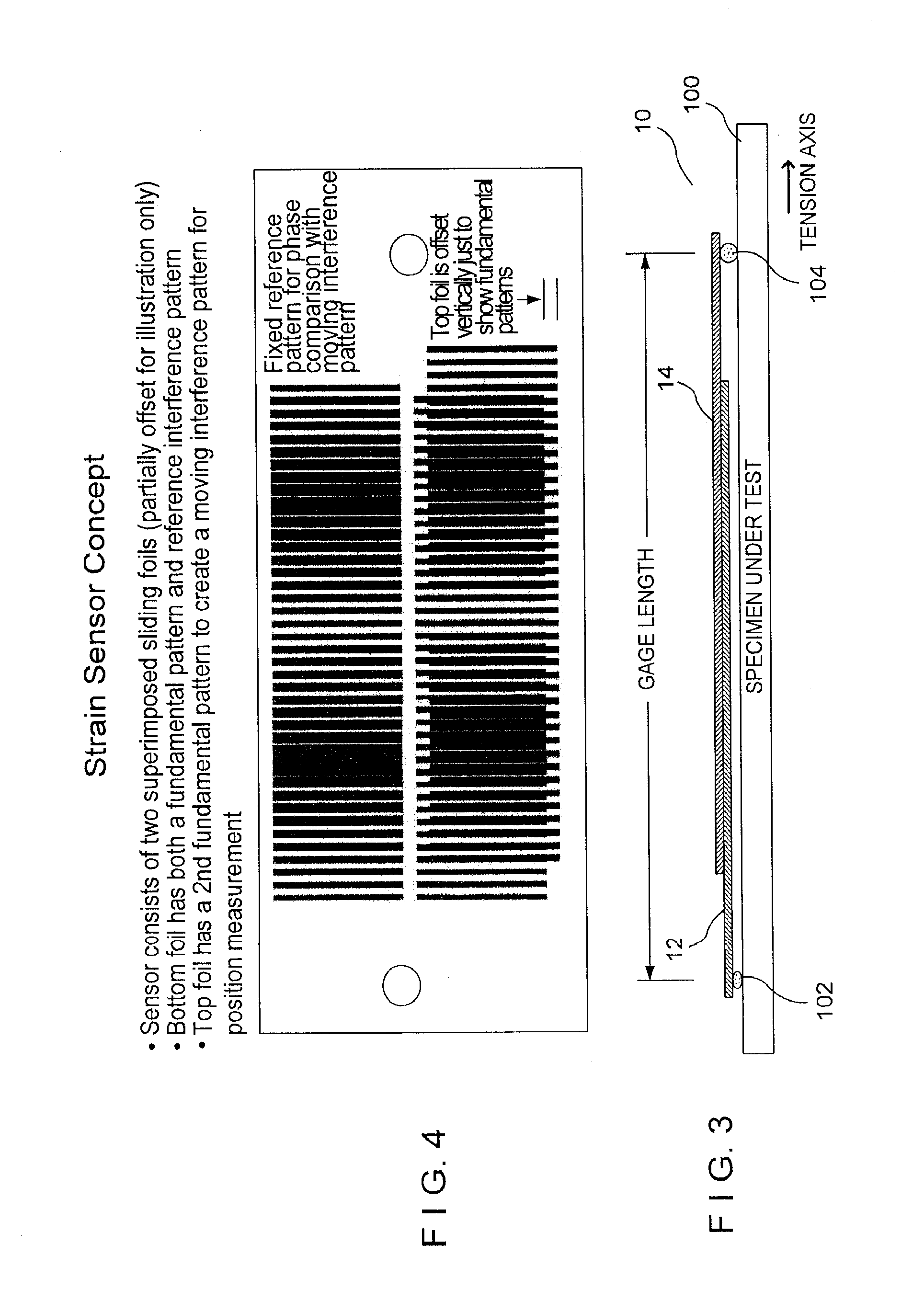
[0028]Referring now to the drawings in detail wherein like numerals indicate like elements throughout the several views, one sees that FIGS. 1-4 illustrate the structure of the strain gauge 10 which is one embodiment of a remote displacement sensor of the present disclosure. FIGS. 1 and 2 illustrate the bottom layer 12 and top layer 14, respectively. The bottom and top layers 12, 14 are typically thin, flexible transparent foils with patterns printed thereon, but other substrates, including rigid substrates, could also be used. The patterns are typically printed on the foils at 2540 dots per inch (10 micrometers per pixel) using established imagesetter technology, or any other suitable method which may vary with the scale or size of the application. Bottom layer 12 includes a first pattern area 16 with parallel lines spaced at a first fundamental frequency of a moiré pattern, while top layer 14 includes a second pattern area 18 with parallel lines spaced at a second fundamental freq...


PUM


Abstract

The disclosure relates to a remote displacement sensor, such as an optical strain gauge, which uses an optical amplifier implemented by patterns, such as, but not limited to, moiré patterns, to calculate changes in position or gauge length. In the embodiment implemented as a strain gauge with moiré patterns, two foil layers are provided, a lower foil layer with a reference or static moiré pattern generated by the overlaying of a first pattern with parallel lines at a first fundamental frequency and a second pattern with parallel lines at a second fundamental frequency. The lower foil layer further includes a first section with a first pattern with parallel lines at the first fundamental frequency while the upper layer provides a second section with a second pattern with parallel lines at the second fundamental frequency. The overlaying of the foils causes an overlying of the first and second sections thereby causing a moiré pattern of the same wavelength as the reference pattern. However, relative movement of the two foils perpendicular to the parallel lines, in response to a movement in the gauge length in response to strain on the specimen, causes a phase change in the overlaid pattern which is greater than the relative movement. The image of the optical strain gauge is captured by a camera or other optical device and the resulting image is processed by a Fast Fourier Transform or similar algorithm to determine the phase change, thereby calculating the change in gauge length and therefore the resulting strain.

Description

[0001]This application claims priority under 35 U.S.C. §119(e) of U.S. provisional application Ser. No. 61 / 243,749 filed Sep. 18, 2009, the disclosure of which is hereby incorporated by reference.BACKGROUND OF THE DISCLOSURE[0002]1. Field of the Disclosure[0003]The present disclosure relates generally to a remote displacement sensor with many applications. In particular, one application is a strain measuring device used in materials testing. More specifically, the present disclosure relates to the use of visual or optical patterns, including but not limited to moiré patterns, which change in appearance in response to changes in position, and to the methods for detecting and interpreting these changes.[0004]2. Description of the Prior Art[0005]In the prior art, strain measuring devices are well known. Instron, a subsidiary of Illinois Tool Works Inc., makes and sells, among other things, various strain measuring devices. In the past, compressive and tensile properties of materials ha...

Claims


Application Information

Patent Timeline
IPC IPC(8): G01B11/14
CPCG01D5/38G01D5/34746G01B11/14
Inventor ALLEN, ROY D.RITTER, MARK A.
Owner ILLINOIS TOOL WORKS INC
Why Eureka
Try Eureka