Fuel cell/ supercapacitor/ battery power system for vehicular propulsion

Inactive Publication Date: 2012-07-26
BY ROSALINDA MARTIENSSEN WERNER OSKAR MARTIENSSEN DECEASED +2
View PDF5 Cites 32 Cited by
  • Summary
  • Abstract
  • Description
  • Claims
  • Application Information

AI Technical Summary

Benefits of technology

[0023]Clearly, there is a need to use our remaining oil supplies wisely—burning what is left in internal combustion engines when a viable alternative exists seems imprudent. However, unless the net energy balance of hybrid-electric, plug-in hybrid electric and all-electric vehicles is positive, i.e., we save more energy by using them in place of ICE-powered cars than we consume to produce their batteries, we are deluding ourselves that the technology is “environmentally friendly.” Furthermore, unless the batteries last at least as long as the rest of the vehicle, many vehicles will be retired earlier than necessary. The longer a battery pack's life, the more likely it will have a net positive energy balance. The limited cycle lives of today's Li-ion and NiMH batteries will require replacement prior to the end-of-life of many vehicles.
[0024]Other than the cost associated with providing a sufficient maximum power output for real world driving situations, there are few disadvantages to vehicles operating on fuel cells. However, it is the purpose of this invention to describe a system that improves on a vehicle operating on a fuel cell alone. For example, if one wishes to make use of regenerative braking or photovoltaic panels on the car's exterior to improve the overall energy efficiency, a battery and/or a capacitor would be required in addition to a fuel cell. The invention described herein uses a new kind of supercapacitor with the energy storage density of an electrochemical battery that is suitable, in combination with a fuel cell, to act as a power system for a vehicle.
[0025]Compared to electrochemical batteries, existing EDL supercapacitors store relatively small amounts of electrical energy per unit mass or volume and they are electrically leaky, meaning that they cannot store their charge over extended periods of time. Until relatively recently, supercapacitors lacked the energy density (energy per unit volume) and specific energy (energy per unit mass) to be used as the primary electrical storage d

Problems solved by technology

Thus, prior art consists of both the power systems used to drive today's vehicles and the supercapacitors themselves: the current state-of-the-art of the latter bei

Method used


Image

  • Fuel cell/ supercapacitor/ battery power system for vehicular propulsion
  • Fuel cell/ supercapacitor/ battery power system for vehicular propulsion
  • Fuel cell/ supercapacitor/ battery power system for vehicular propulsion

Examples


Embodiment Construction

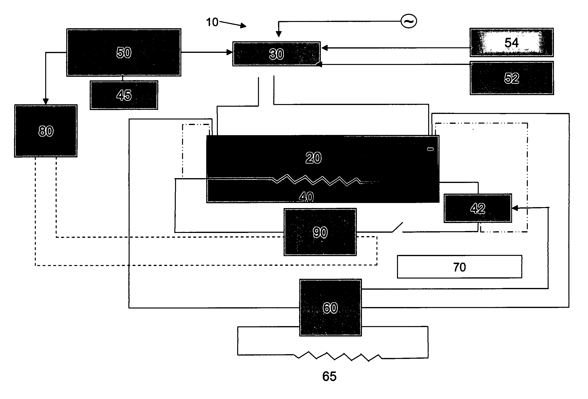
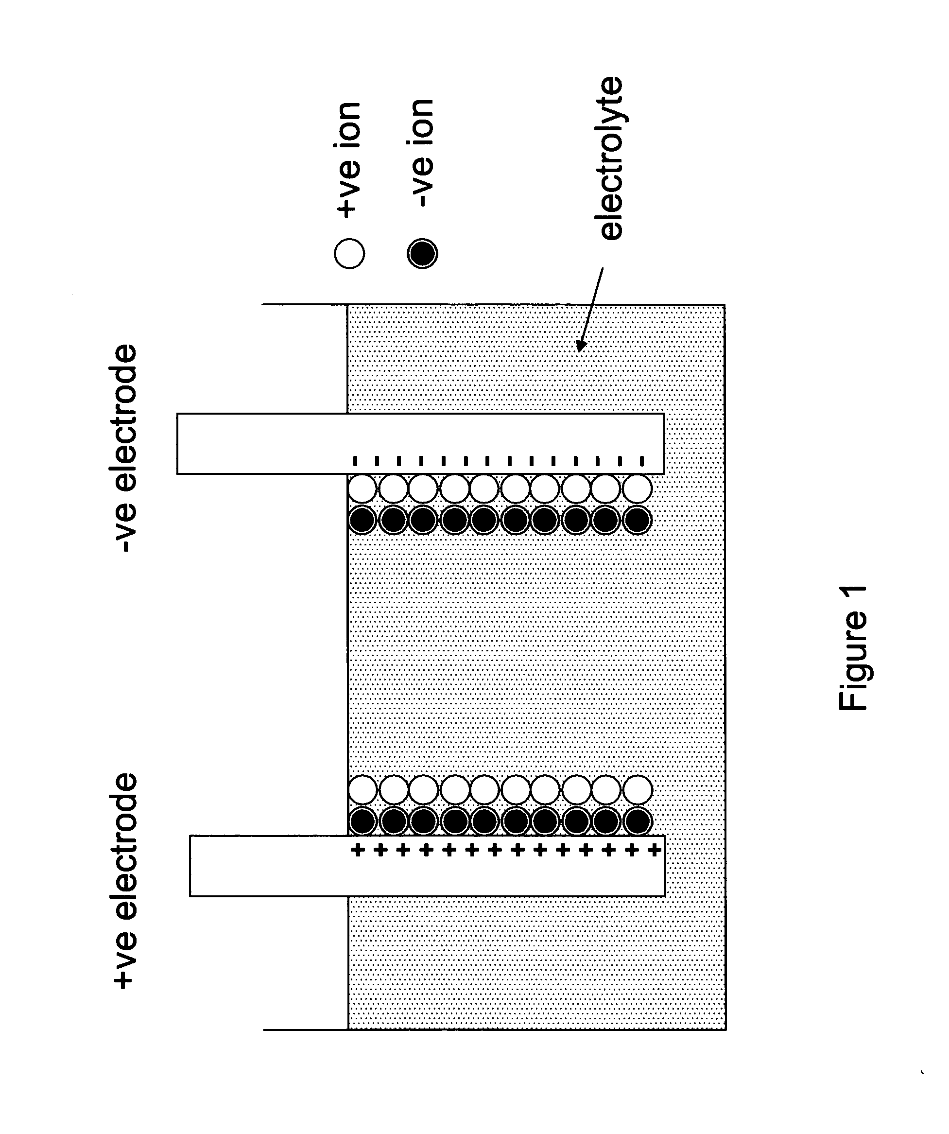
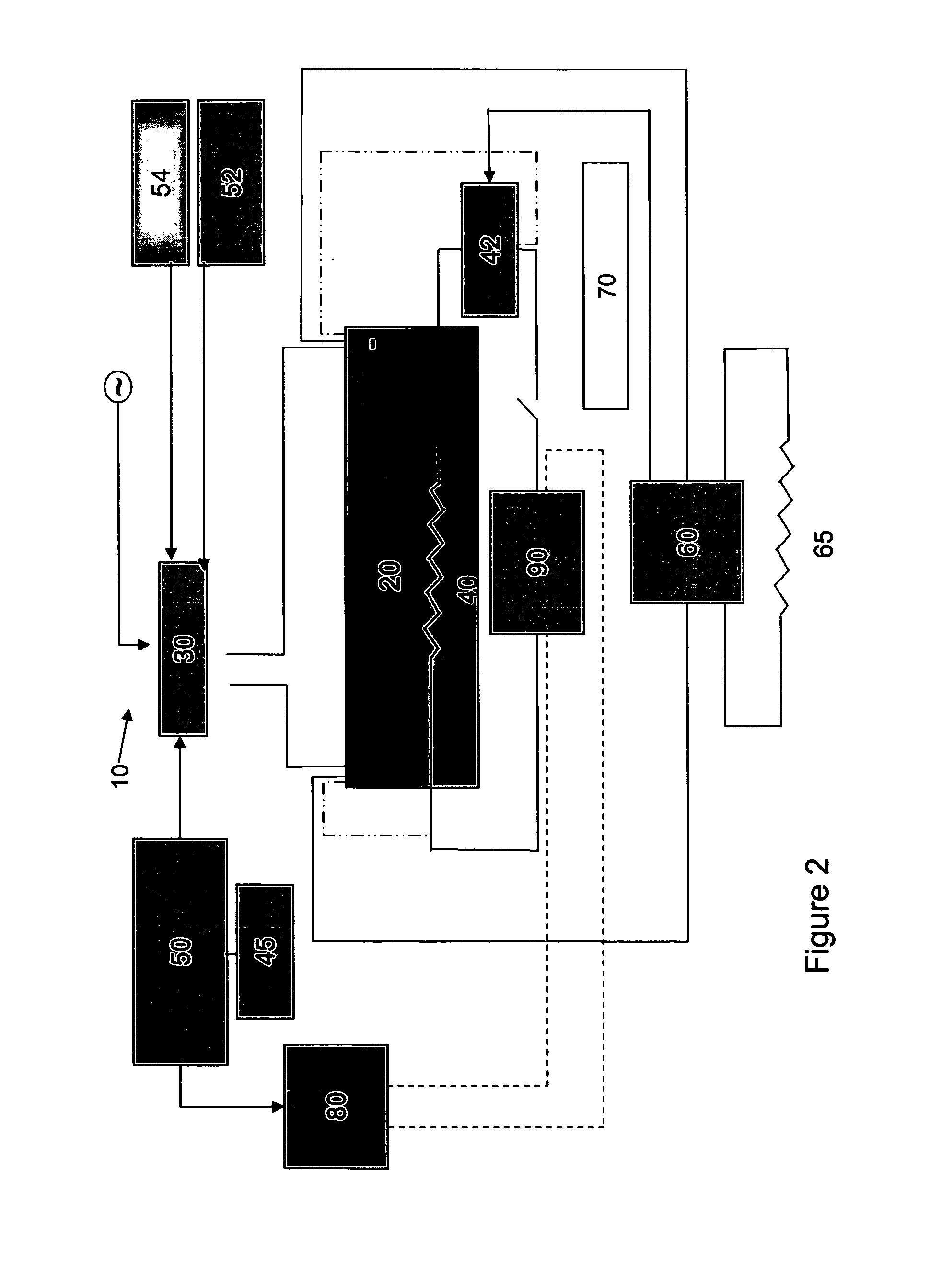
[0051]The current invention describes a device structure and manufacturing method to fabricate an electrochemical double layer supercapacitor with a molten salt electrolyte: we prefer to call this device an electronic battery, because although it behaves like a capacitor, storing charge at the interface between the electrodes and dielectric, the amounts of energy that can be stored per unit volume (energy density) and per unit mass (specific energy) are more typical of a battery than a capacitor. The electronic battery is made by combining metallic powders and molten salt electrolytes to form the composite electrode structures; every other pair of electrodes is separated by a thin dielectric. Although this device is primarily intended to be incorporated into a system for electric vehicle propulsion, the device can also be made as a thin-film stack, making it suitable for use in place of thin-film batteries for some MEMS (Micro-ElectroMechanical Systems), SiP (System in a Package) an...


PUM

PropertyMeasurementUnit
Melting pointaaaaaaaaaa
Electrical conductoraaaaaaaaaa

Abstract

The present invention provides a power system for a vehicle The power system comprising a supercapacitor-like electronic battery that is connected to a battery charger. The battery charger provides energy to the supercapacitor-like electronic battery. A heater is operatively connected to the supercapacitor-like electronic battery to provide energy to heat the supercapacitor-like electronic battery thereby lowering the internal impedance of the supercapacitor-like electronic battery. A charging apparatus is operatively connected to the battery charger. A motor is operatively connected to the vehicle and the supercapacitor-like electronic battery. A feedback loop controller is operatively connected to the heater, the supercapacitor-like electronic battery and the motor.

Description

CROSS REFERENCES TO RELATED APPLICATIONS[0001]This application claims priority from and is related to commonly owned U.S. Provisional patent application Ser. No. 61 / 232,068 filed Aug. 7, 2009, entitled: All Solid-State Electrochemical Double Layer Supercapacitor, and U.S. Provisional patent application Ser. No. 61 / 232,071 filed Aug. 7, 2009, entitled: Fuel Cell / Supercapacitor / Battery Power System for Vehicular Propulsion, these Provisional Patent Applications incorporated by reference herein.FIELD OF THE INVENTION[0002]The present invention relates to solid-state energy-storage devices, and, more particularly, to electrolyte films in such devices. This invention also relates to methods and systems for using these storage devices to propel vehicles.BACKGROUND OF THE INVENTION[0003]The world's known oil reserves are dwindling at an ever increasing rate as developing nations industrialize and demand increases. The price of oil exceeded $100 per barrel in 2008 and is very likely to bec...

Claims


Application Information

Patent Timeline
IPC IPC(8): H02J7/00B82Y99/00
CPCH01G9/038Y10T29/435H01G9/155H01G11/00H01G11/04H01G11/24H01G11/56H01G11/70Y02E60/13Y02T10/7022H01G9/0029H01G2009/0014H01G11/78Y10T29/43Y10T29/49112Y10T29/49002Y10T29/49108H01G9/058Y02T10/70Y02P70/50H01G11/84H01G11/22H01G9/15
Inventor MARTIENSSEN, WERNER OSKARMARTIENSSEN, ROSALINDAREYNOLDS, GLYN JEREMY
Owner BY ROSALINDA MARTIENSSEN WERNER OSKAR MARTIENSSEN DECEASED
Why Eureka
Try Eureka