System and method for optical imaging with vertical cavity surface emitting lasers

a laser and cavity surface technology, applied in the field of optical imaging technologies, can solve the problems of frequent imaging, reduced image quality, and reduced image quality, and achieve the effect of reducing spatial noise and temporal nois

Active Publication Date: 2012-07-26
THE GOVERNINIG COUNCIL OF THE UNIV OF TORANTO
View PDF16 Cites 32 Cited by
  • Summary
  • Abstract
  • Description
  • Claims
  • Application Information

AI Technical Summary

Benefits of technology

[0010]In a first aspect of the invention, an optical imaging system is operable to alternate the operation of at least one multi-modal, multi-wavelength laser light source between at least two different modalities, such as intrinsic optical signal imaging (IOSI) and laser speckle contrast imaging (LSCI), thereby enabling the reduction of spatial noise and temporal noise in resulting capture images.

Problems solved by technology

However, these technologies generally require the subject to be scanned to be immobile.
However, in infants or animal models, immobilization often requires the use of a sedative or anaesthetic.
Due to the negative physiological effects of these drugs, especially in immunocompromised subjects, frequent imaging can have physiologically detrimental or even fatal consequences.
Another common but widely accepted problem with prior art imaging devices is their size and significant cost (hardware, software, and associated support and training costs).
Also, due to bulky, fixed implementation, subjects must be brought to the device—it cannot be brought to them.
This limits the applications of optical imaging technologies.
Yet another problem is the need to use different imaging modalities in order to enable capture of different types of images and a series of images captured over time for making a required diagnosis.
Performing multiple scans in series using different imaging modalities can significantly increase the time and costs for performing scans for a given subject.

Method used


Image

  • System and method for optical imaging with vertical cavity surface emitting lasers
  • System and method for optical imaging with vertical cavity surface emitting lasers
  • System and method for optical imaging with vertical cavity surface emitting lasers

Examples


example of implementation

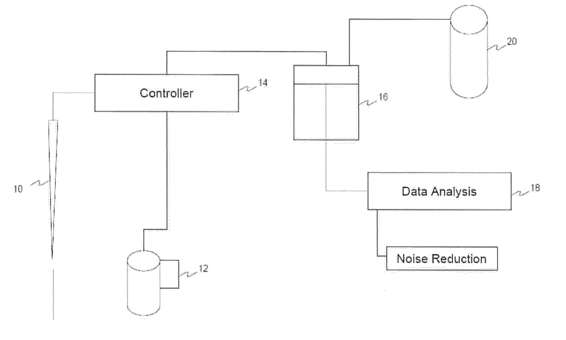
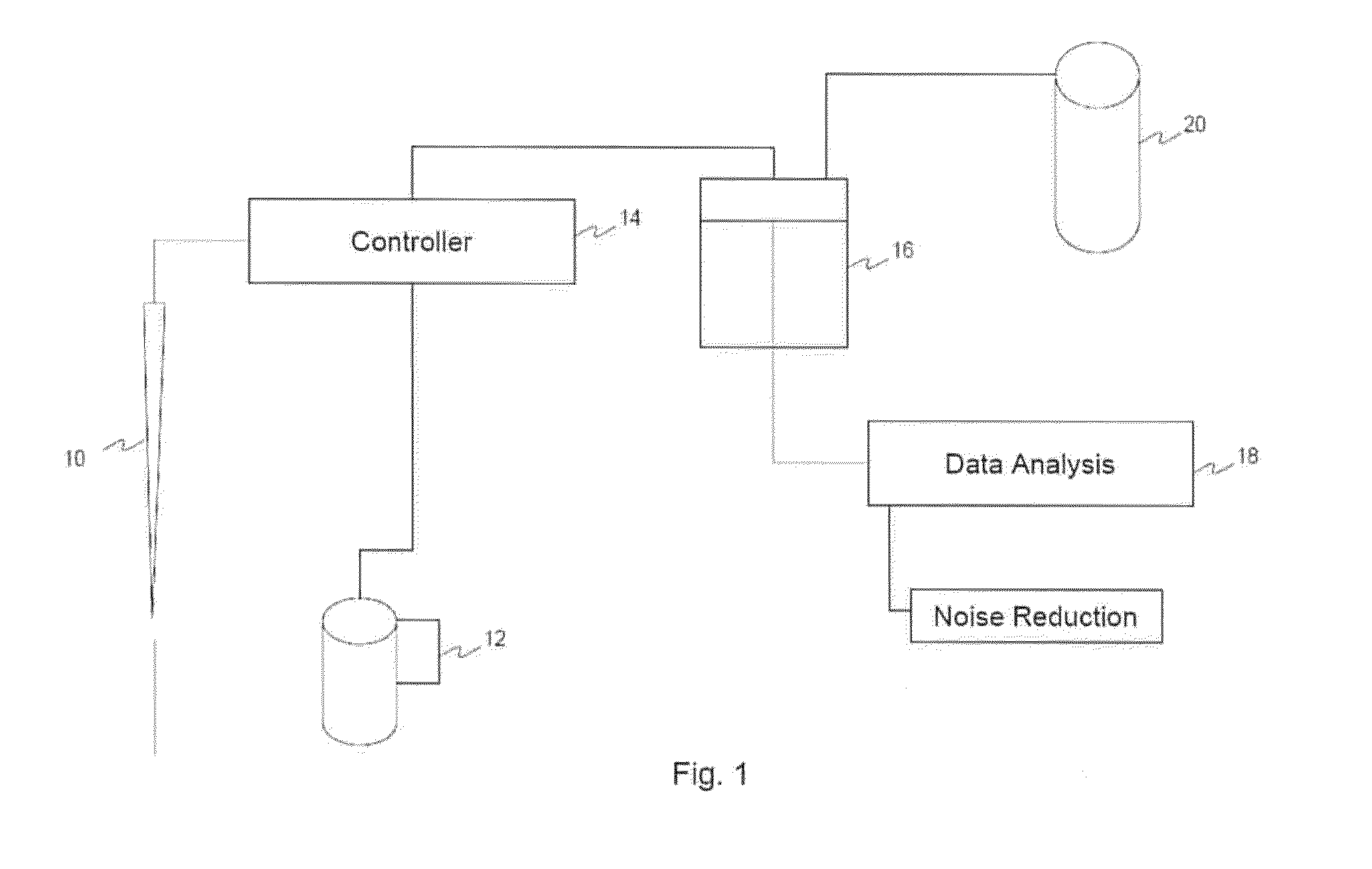
[0049]The invention is further explained by reference to an example of an implementation thereof. The results indicated below are based on use of the example implementation.

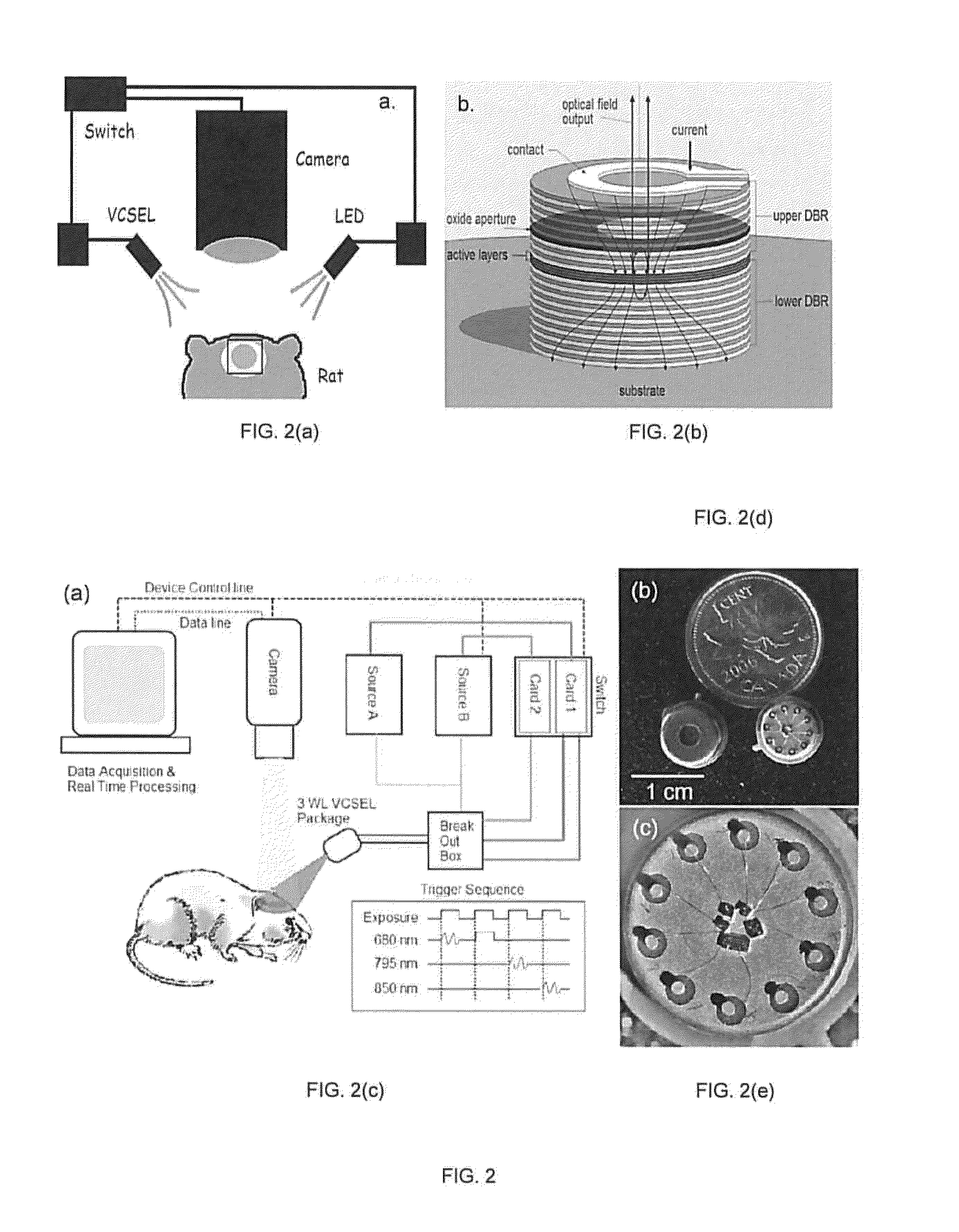
[0050]In one implementation, oxide-confined VCSELs are used, which are available commercially, and provide wavelengths as low as 670 nm, power levels in excess of 1 mwatt, a circular beam shape, low noise, over a GHz modulation bandwidth, and good control of the mode shape and optical beam properties. Such VCSELs are stable and have low values of relative intensity noise (RIN). Power efficiency, small size, and low operating currents of VCSELs. (˜few mA) minimize the required operating power, and heat dissipation requirements, further improving the suitability of VCSELs attractive for optical imaging applications.

[0051]The VCSEL may be powered by a Keithley 6221 current source, with waveform capability. A silica-based tissue phantom may be used as a uniform reflecting surface, to allow evaluation and optimization...


PUM


Abstract

The present invention uses vertical-cavity surface-emitting lasers (VCSELs) as illumination source for simultaneous imaging of blood flow and tissue oxygenation dynamics in vivo, or a means to monitor neural activity in brain slices ex vivo. The speckle pattern on the brain tissue due to a VCSEL's coherence properties is the main challenge to producing low-noise high-brightness illumination, required for evaluating tissue oxygenation. Moreover, using oxide-confined VCSELs we show a fast switching from a single-mode operation scheme to a special multi-modal, multi-wavelength rapid sweep scheme. The multi-modal, multi-wavelength rapid sweep scheme reduces noise values to within a factor of 40% compared to non-coherent LED illumination, enabling high-brightness VCSELs to act as efficient miniature light sources for various brain imaging modalities and other imaging applications. These VCSELs are promising for long-term portable continuous monitoring of brain dynamics in freely moving animals.

Description

CROSS-REFERENCE TO RELATED APPLICATIONS[0001]The present application, claims the benefit under 35 U.S.C. §119(e) of U.S. Provisional Application Ser. No. 61 / 435,453 filed on Jan. 24, 2011, titled “SYSTEM AND METHOD FOR OPTICAL IMAGING WITH VERTICAL CAVITY SURFACE EMITTING LASERS”, attorney docket No. 062108.0225, the entirety of which is hereby incorporated by reference.FIELD OF THE INVENTION[0002]This invention relates generally to optical imaging technologies. This invention relates more particularly to intrinsic optical signal imaging devices and methods.BACKGROUND OF THE INVENTION[0003]Current biomedical imaging modalities, including functional magnetic resonance imaging, computed tomography scan, and positron emission tomography, are mature imaging technologies that produce useful data for medical diagnostics and basic biomedical research. However, these technologies generally require the subject to be scanned to be immobile. For adult human subjects, this is easily achieved. H...

Claims


Application Information

Patent Timeline
Patent Type & Authority Applications(United States)
IPC IPC(8): H04N7/18H04N5/232
CPCH04N5/332H04N5/2256H04N23/56H04N23/11
Inventor MUNRO, ELIZABETH ALICELEVI, OFER
Owner THE GOVERNINIG COUNCIL OF THE UNIV OF TORANTO
Why Eureka
Try Eureka