Cutting insert, cutting tool, and method of manufacturing machined product using the same

a cutting tool and cutting edge technology, applied in the direction of turning machine accessories, manufacturing tools, shaping cutters, etc., can solve the problem of increasing cutting resistance in the region, and achieve the effect of reducing cutting resistance, improving cutting edge strength, and reducing vibration

Active Publication Date: 2012-07-26
KYOCERA CORP
View PDF7 Cites 31 Cited by
  • Summary
  • Abstract
  • Description
  • Claims
  • Application Information

AI Technical Summary

Benefits of technology

[0011]In the cutting insert according to one embodiment, the cutting edge includes sequentially the ascending portion, the top portion, and the descending portion, in a direction from the flat cutting edge to the major cutting edge in the side view. It is therefore capable of improving cutting edge strength. Further, besides the major cutting edge, the minor cutting edge having the larger peripheral cutting edge angle than the major cutting edge is interposed between itself and the flat cutting edge. It is therefore capable of reducing cutting resistance. As a result, vibration occurrence is reduced even in high speed cutting, such as high feed, and hence cutting edge fracture is reduced, thereby achieving life

Problems solved by technology

However, when this cutting insert is attached to a holder, there is a risk that a region having a negative axial rake angle occurs in th

Method used


Image

  • Cutting insert, cutting tool, and method of manufacturing machined product using the same
  • Cutting insert, cutting tool, and method of manufacturing machined product using the same
  • Cutting insert, cutting tool, and method of manufacturing machined product using the same

Examples


first embodiment

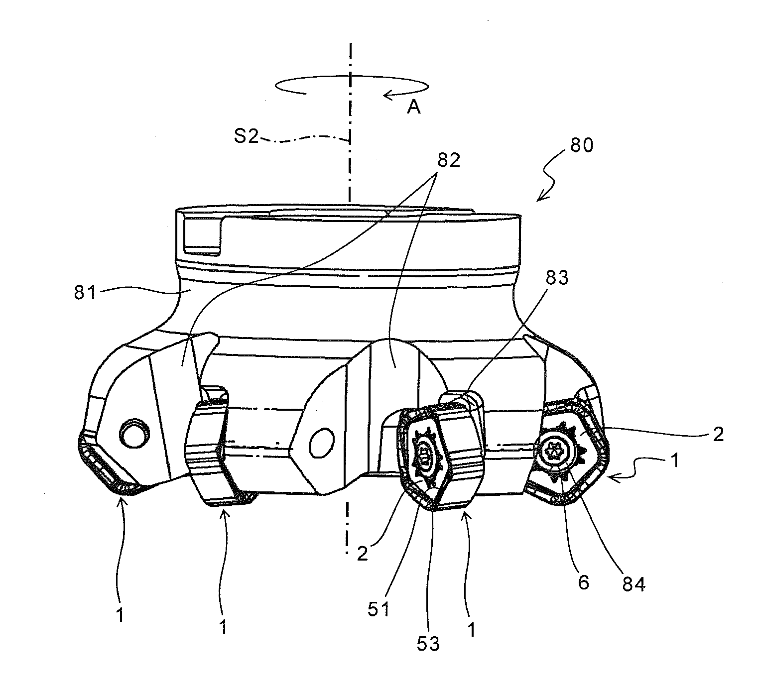
[0075]Next, a first embodiment of the cutting tool according to the present invention is described in detail with reference to FIGS. 9 and 10. As shown in FIGS. 9 and 10, the cutting tool 80 (rotary cutting tool) according to the present embodiment is configured to attach a plurality of inserts 1 to a holder 81.

[0076]To be specific, a plurality of circumferentially spaced insert pockets 82 are formed at a peripheral front end of the holder 81. These insert pockets 82 are portions obtained by cutting off the holder 81 into a substantially V-shape when viewed from the front end. The inserts 1 are respectively attached to a plurality of attachment surfaces 83 formed thereby.

[0077]For example, the attachment thereof is carried out by inserting an attachment screw 84 into the through hole 6 of each insert 1, and then screwing the attachment screw 84 into a female screw formed in the attachment surface 83 of the holder 81, or by allowing the attachment screw 84 to pass through a through h...

second embodiment

[0079]A second embodiment of the cutting tool according to the present invention is described in detail with reference to FIG. 11. In FIG. 11, the same components as the foregoing FIGS. 9 and 10 are identified by the same reference numerals, and the description thereof is omitted here.

[0080]As shown in FIG. 11, the cutting tool 85 according to the present embodiment is made up of a holder 86 having substantially the same configuration as the holder 81 according to the first embodiment, and the inserts 1 attached to the holder 86.

[0081]In the holder 86 of the present embodiment, the major cutting edge 51 of the insert 1 is brought into contact with the workpiece 100 at a relatively gentle inclination of approximately 30°. Axial rake angles of the major cutting edge 51 and the minor cutting edge 53 with respect to a rotation axis of the holder 86 are negative from the viewpoint of ensuring high strength of the cutting edge 5. In the present embodiment, the minor cutting edge 53 having...

third embodiment

[0083]A third embodiment of the cutting tool according to the present invention is described in detail with reference to FIGS. 12 and 13. In FIGS. 12 and 13, the same components as the foregoing FIGS. 9 to 11 are identified by the same reference numerals, and the description thereof is omitted here. As shown in FIGS. 12 and 13, the cutting tool 90 according to the present embodiment is configured to attach a plurality of inserts 11 to a holder 91.

[0084]To be specific, a plurality of circumferentially spaced insert pockets 92 are formed at a peripheral front end of the holder 91 similarly to the holder 81 of the first embodiment. These inserts 1 are respectively attached to a plurality of attachment surfaces 93 of these insert pockets 92.

[0085]Each insert 11 is attached to the holder 91 by orienting the upper surface 12 ahead in the rotation direction indicated by arrow A, and allowing the major cutting edge 151 to protrude from the periphery of the holder 91. The insert 11 is prefer...


PUM

PropertyMeasurementUnit
Angleaaaaaaaaaa
Angleaaaaaaaaaa
Lengthaaaaaaaaaa

Abstract

A cutting insert according to an embodiment of the present invention includes an upper surface; a lower surface; a side surface; and a cutting edge which is located in an intersection region of the upper surface and the side surface, and includes a major cutting edge, a flat cutting edge, and a minor cutting edge located between the major cutting edge and the flat cutting edge. The cutting edge reaches a top portion thereof while being inclined upward from the flat cutting edge to the major cutting edge with respect to a reference plane perpendicular to a central axis of the cutting insert in a side view. The cutting edge is thereafter inclined downward with respect to the reference plane. A peripheral cutting edge angle of the minor cutting edge is larger than a peripheral cutting edge angle of the major cutting edge. A cutting tool including the cutting insert; and a method of manufacturing a machined product using the cutting tool are provided.

Description

TECHNICAL FIELD[0001]The present invention relates to a cutting insert, a cutting tool, and a method of manufacturing a machined product using the same.BACKGROUND ART[0002]As an example of cutting inserts used for face milling cutters and end mills, for example, Japanese Unexamined Patent Publication No. 2010-523353 discloses a double-sided cutting insert including a major cutting edge 50 and a minor cutting edge 52.[0003]However, when this cutting insert is attached to a holder, there is a risk that a region having a negative axial rake angle occurs in the vicinity of an upper end 58 of the major cutting edge 50, thus causing the problem that cutting resistance is increased in the region.[0004]Hence there is a desire for a cutting insert that can further reduce the cutting resistance than conventional ones.SUMMARY OF THE INVENTION[0005]An object of the present invention is to provide a cutting insert and a cutting tool, which have both high cutting edge strength and low cutting res...

Claims


Application Information

Patent Timeline
IPC IPC(8): B23C5/20B23B27/22B23C5/06B23B27/16
CPCB23C5/06B23C5/202B23C2200/0444B23C2200/203B23C2200/208Y10T407/235Y10T407/2272Y10T407/23Y10T409/303808Y10T407/1924B23C2200/366
Inventor XU, YONGBO
Owner KYOCERA CORP
Why Eureka
Try Eureka