Wind turbine with a braking device and method for braking at least one drive train component of a drive train, and use of a braking device for braking at least one drive train component of a drive train of a wind turbine

a technology of wind turbines and braking devices, which is applied in the direction of rotors, marine propulsion, vessel construction, etc., can solve the problems of high degree of technical and material complexity, braking devices in wind turbines are subjected throughout their lifetime not only to rotational forces but also to other powerful mechanical stresses, etc., and achieves compact system and increase in braking force

Inactive Publication Date: 2012-07-26
SIEMENS AG
View PDF7 Cites 4 Cited by
  • Summary
  • Abstract
  • Description
  • Claims
  • Application Information

AI Technical Summary

Benefits of technology

[0037]However, the zigzag shape need not necessarily be an angular zigzag, but can also be rounded. In other words, the guide surface and / or the brake wedge surface can have peaks and valleys, so that the brake wedge can be moved against the guide surface from an initial zero point in two different directions in order to achieve an increase in braking force. With this alternative, tighter contact between the guide surface and the brake wedge is possible; this enables a more compact system to be implemented, as it is consequently more stable because the brake wedge cannot, for example, escape completely from the guide surface in one direction.

Problems solved by technology

However, in various hazardous situations, i.e. critical operating situations of the wind turbine it is necessary for the drive train to be braked.
This is necessary particularly if individual components of the wind turbine are inoperative and further damage may be caused by rotation of the drive train.
These people usually work in the nacelle of the wind turbine and rotation of the drive train both hinders their work and exposes them to severe danger due to the enormous forces caused by said rotation.
Moreover, braking devices in wind turbines are subject throughout their lifetime not only to the rotational forces but also to other powerful mechanical stresses such as vibrations, resonance effects and damping effects.
This means that both the pneumatic or hydraulic system of braking devices in wind turbines and the cooling or filtering equipment involve a high degree of technical and material complexity, resulting in exacting requirements in terms material, mounting space inside the cabin of the wind turbine, weight and cost.
In spite of these efforts, because of the inertia of the hydraulic or pneumatic transmission means and the very difficult to control quality differences between the solenoid valves, adequate and precise control of the (above described) braking devices is very difficult to guarantee.

Method used


Image

  • Wind turbine with a braking device and method for braking at least one drive train component of a drive train, and use of a braking device for braking at least one drive train component of a drive train of a wind turbine
  • Wind turbine with a braking device and method for braking at least one drive train component of a drive train, and use of a braking device for braking at least one drive train component of a drive train of a wind turbine
  • Wind turbine with a braking device and method for braking at least one drive train component of a drive train, and use of a braking device for braking at least one drive train component of a drive train of a wind turbine

Examples


Embodiment Construction

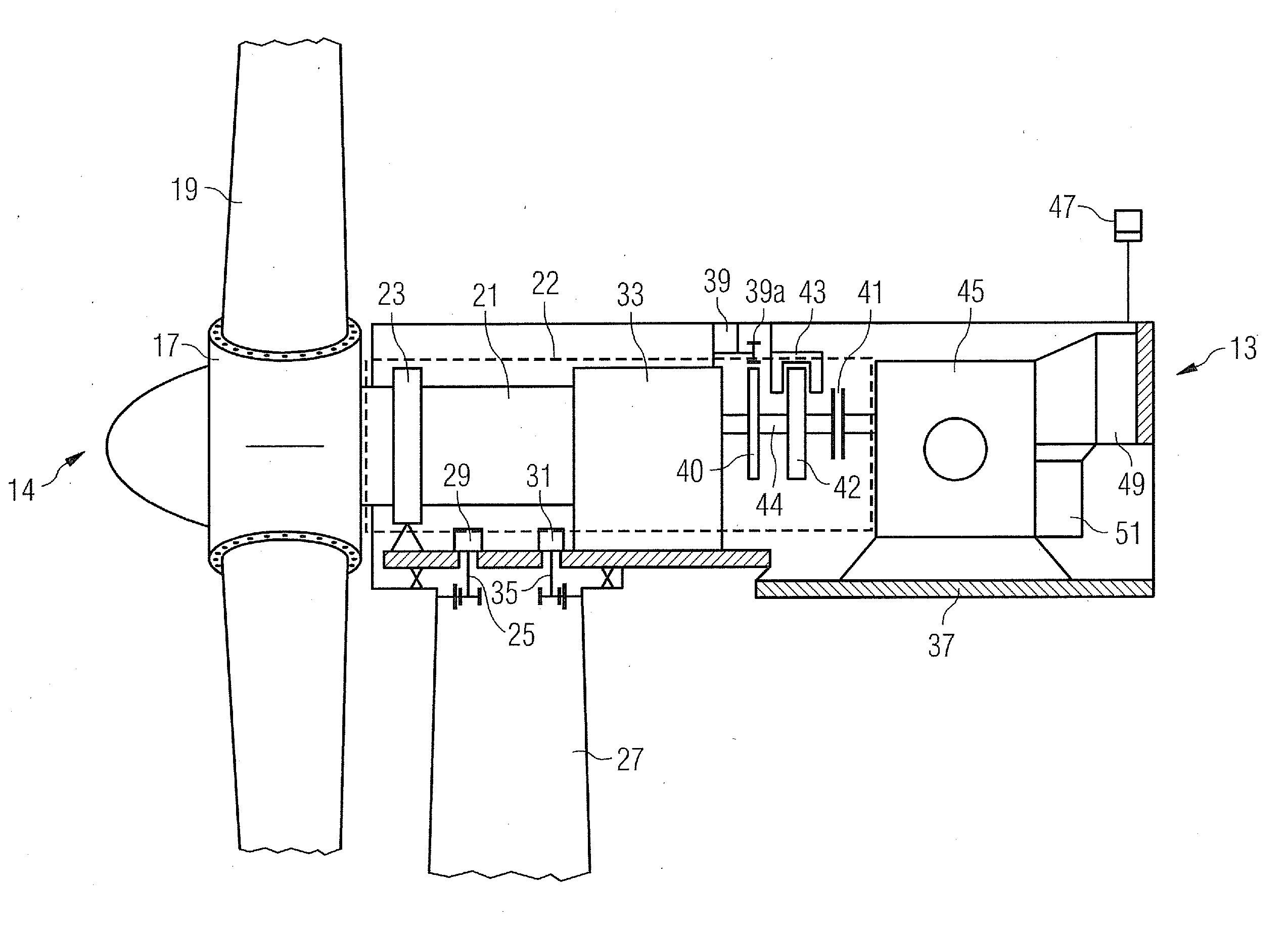
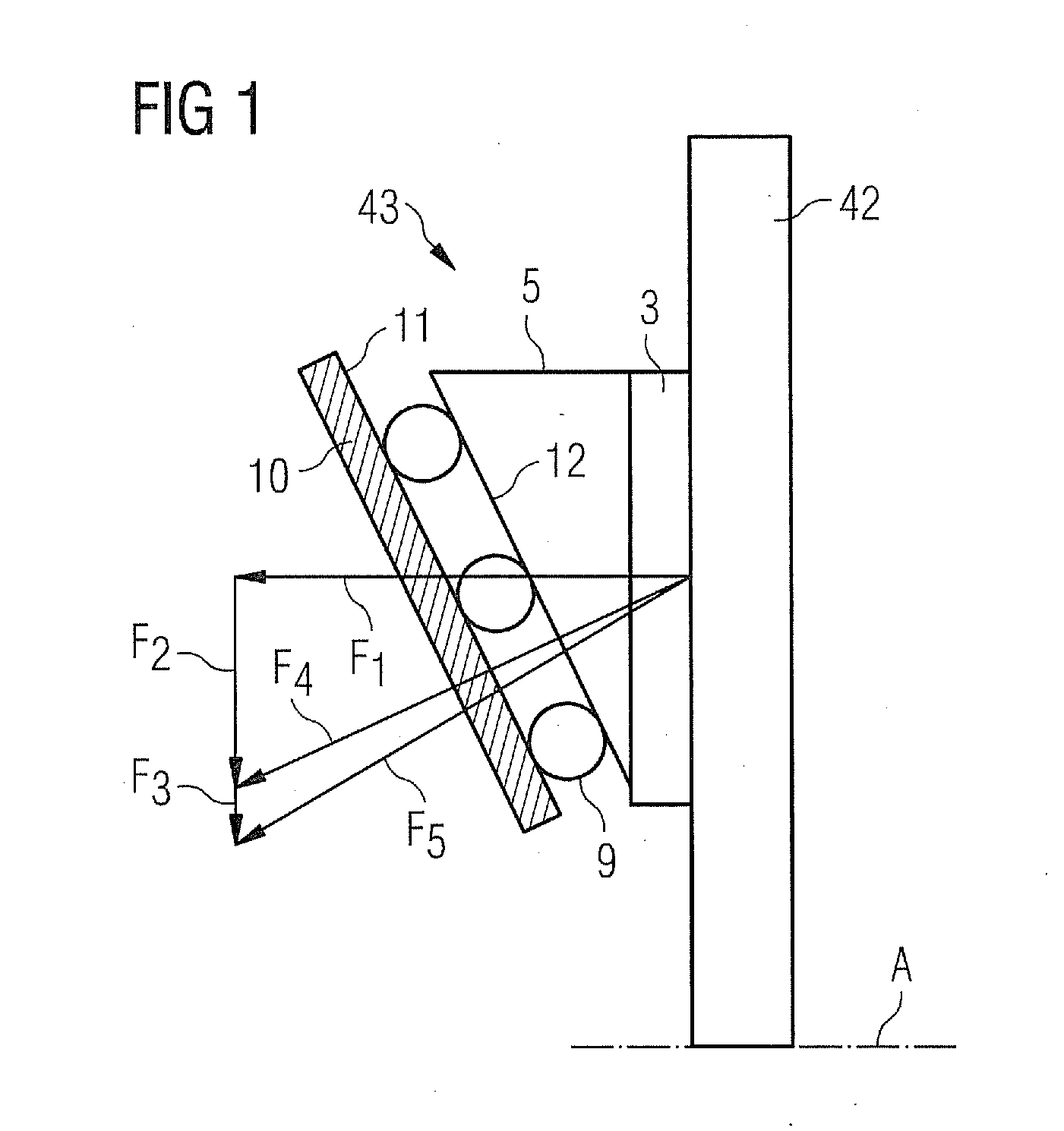
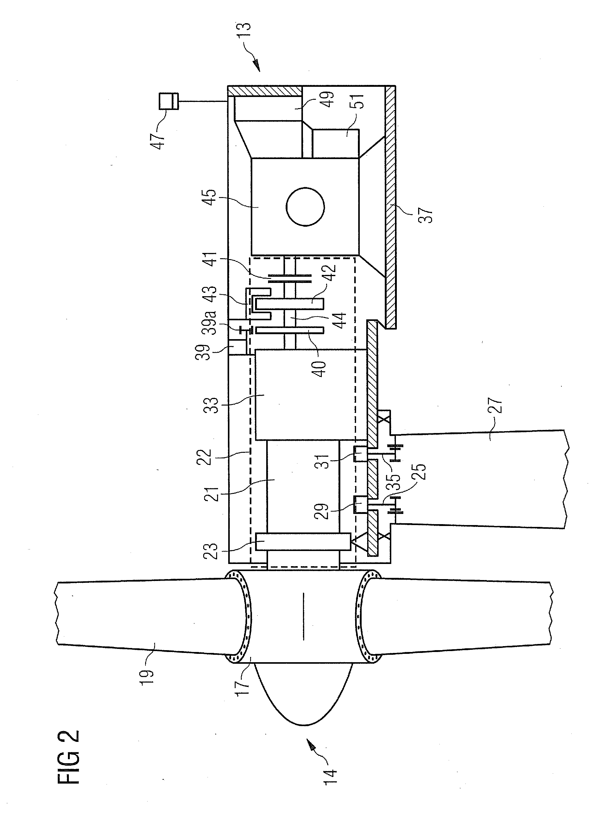
[0045]FIG. 1 shows a schematic side view of a wedge brake 43. It comprises a brake wedge 5 which moves on rollers 9 along a guide plane 11 of a support structure 10. A surface or bearing surface 12 of the brake wedge 5 faces in the direction of the guide plane 11 along which the rollers 9 are mounted. On the side of the brake wedge 5 opposite the bearing surface 12 is a brake pad 3 facing in the direction of a brake disk 42. The brake disk 42 rotates about an axis A to which the guide plane 11 is aligned obliquely, i.e. at an angle of neither 180° nor 90°. This means that the brake disk 42 rotates in the direction of the viewer's line of sight.

[0046]When the brake wedge 5 lies with the brake pad 3 pressed against the brake disk 42, a normal force F1 and a frictional force F2 tangential to the normal force F1 are applied to the brake disk 42. In a triangle of forces, the combination of these two forces F1, F2 results in a combined braking force F4. The braking of the brake disk 42 ta...


PUM


Abstract

A braking device and method are provided for a wind turbine. The wind turbine includes a rotor, a generator and a drive train having one or more components. The drive train is connected to the generator for obtaining electrical energy from rotation of the drive train. The wind turbine further includes a braking device for braking at least one drive train component of the drive train. The braking device includes a wedge brake.

Description

CROSS REFERENCE TO RELATED APPLICATIONS[0001]This application claims priority of European Patent Office application No. 11151849.4 EP filed Jan. 24, 2011. All of the applications are incorporated by reference herein in their entirety.FIELD OF INVENTION[0002]The present invention relates to a wind turbine comprising a rotor and at least one drive train which is connected to a generator for obtaining electrical energy from rotation of the drive train, and having a braking device for braking at least one drive train component of the drive train. It also relates to a method for braking at least one drive train component of a drive train of a wind turbine having a rotor and at least the drive train which is connected to a generator for obtaining electrical energy from rotation of the drive train. It also relates to the use of a braking device for braking at least one drive train component of a drive train of a wind turbine comprising a rotor and at least the drive train which is connecte...

Claims


Application Information

Patent Timeline
Patent Type & Authority Applications(United States)
IPC IPC(8): F03D7/00F03D11/00F03D9/00
CPCF03D7/0248F03D11/00F05B2260/902F16D65/0012Y02E10/723F16D2127/10F16D65/18F16D2125/40Y02E10/722F16D2121/24F03D80/00Y02E10/72F03D9/25F03D17/00
Inventor WOHLLEB, MATTHIAS
Owner SIEMENS AG
Why Eureka
Try Eureka