Connector and connector assembly used for transmitting low-speed signal and/or high-speed signal

a technology of low-speed signal and connector assembly, which is applied in the direction of coupling device connection, engagement/disengagement of coupling parts, printed circuit aspects, etc., can solve the problems of easily affecting transmission quality and limited overall thickness of conventional sata connector, and achieve the effect of advancing transmission quality and reducing overall thickness

Active Publication Date: 2012-07-26
BING XU PRECISION
View PDF4 Cites 31 Cited by
  • Summary
  • Abstract
  • Description
  • Claims
  • Application Information

AI Technical Summary

Benefits of technology

[0007]Accordingly, the present invention is directed to a connector and a connector assembly, in which in comparison with the prior art, the connector after assembling has a reduced overall thickness...

Problems solved by technology

Moreover, the connector 1 is vertically assembled into the connector 2, the overall thickness of the conventional SATA connector is limited to be reduced and the design ...

Method used


Image

  • Connector and connector assembly used for transmitting low-speed signal and/or high-speed signal
  • Connector and connector assembly used for transmitting low-speed signal and/or high-speed signal
  • Connector and connector assembly used for transmitting low-speed signal and/or high-speed signal

Examples


first embodiment

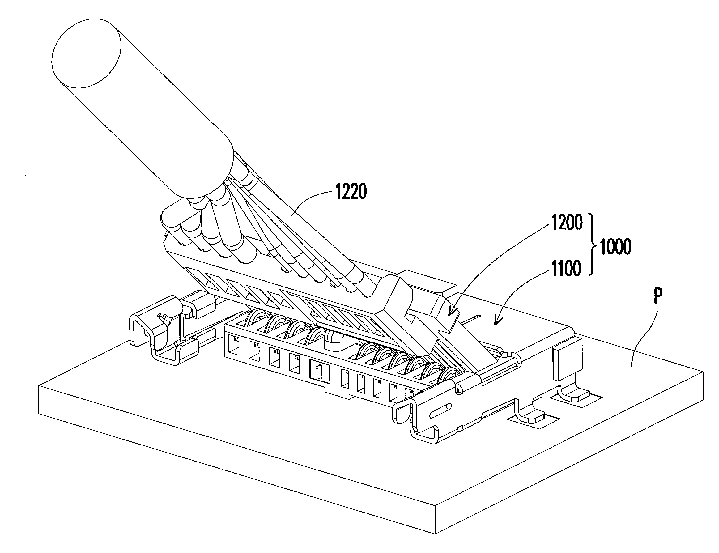
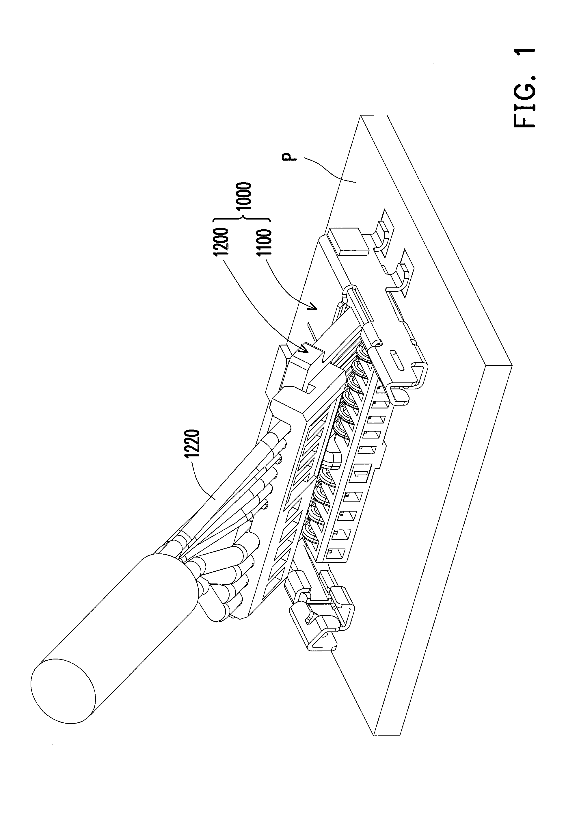
[0053]FIG. 1 is a perspective view of a connector assembly 1000 according to the present invention. Referring to FIG. 1, the connector assembly 1000 includes a board-side connector 1100 and a cable-side connector 1200. The board-side connector 1100 is suitable to be fixed to a motherboard. P and the cable-side connector 1200 is suitable to assist the motherboard P and other apparatuses in performing electronic signals transmission.

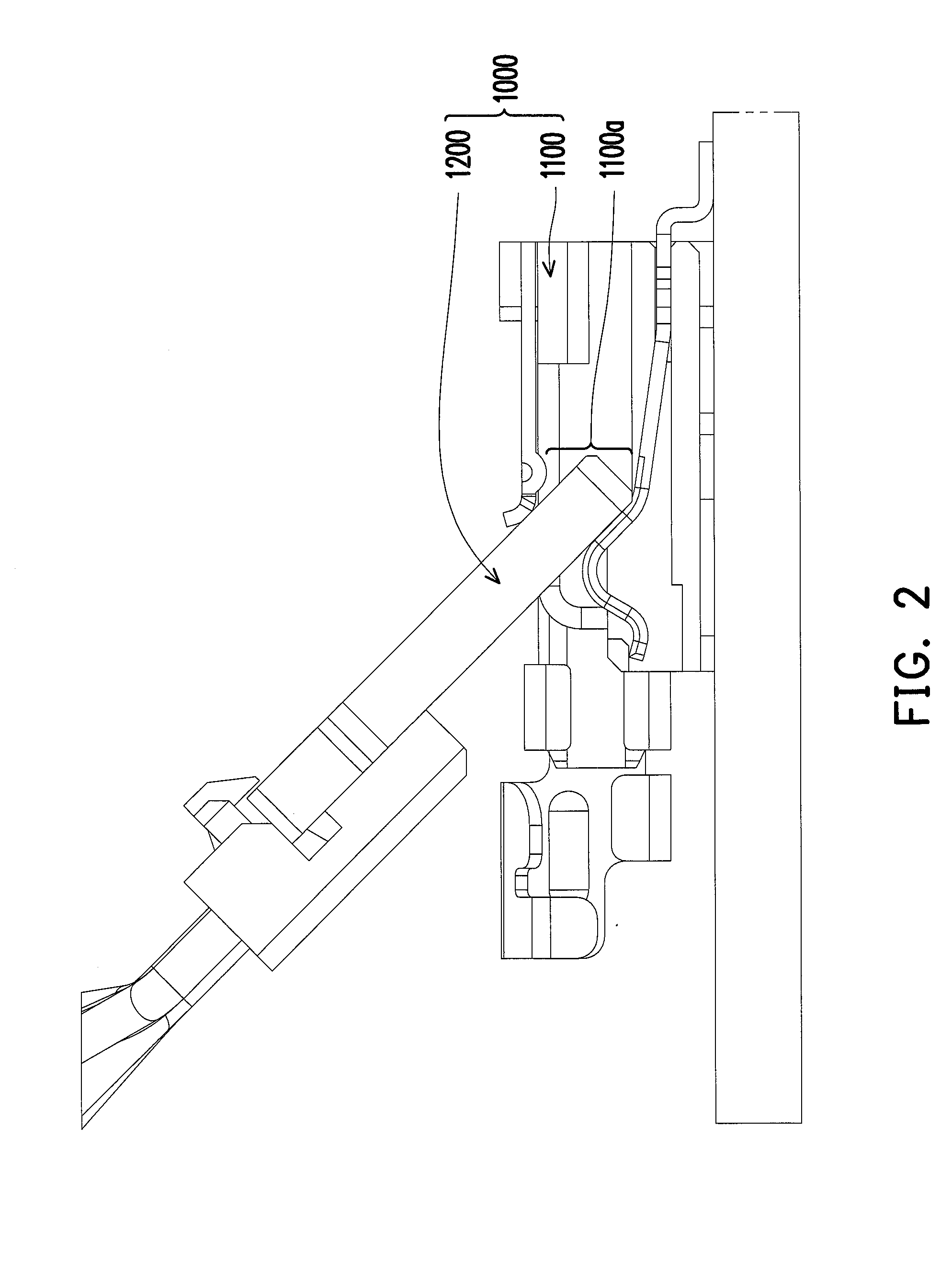
[0054]Referring to FIG. 2, the board-side connector 1100 has an obliquely guiding path 1100a for the cable-side connector 1200 to be obliquely inserted and assembled to the board-side connector 1100. In this way, when the cable-side connector 1200 is assembled to the board-side connector 1100 along the obliquely guiding path 1100a, the assembling job can be done more handy and easier. In addition, the overall height of the connector assembly 1000 after assembling the cable-side connector 1200 and the board-side connector 1100 can be reduced

[0055]Referring ...

second embodiment

[0069]In the invention, a shielding shell 2130 is disclosed as shown by FIGS. 7A and 7B. Referring to FIGS. 7A and 7B, for simplicity, the printed circuit board and the cables are omitted in FIG. 7B. An electrical leaning portion 2130a-1 and four portions of an upper position-limitation portion 2130a-1, an inward protrusive portion 1130b-1, a lower position-limitation portion 2130b-2 and a forward-backward position-limitation portion 2130c of a structure position-limitation portion 2130b are formed by bending parts of the shielding shell 2130 and located at both sides of the shielding shell 2130. The difference of the upper position-limitation portion 2130a-1 of the shielding shell 2130 in the embodiment from the upper position-limitation portion 1130a-1 of the shielding shell 1130 in FIG. 6A rests in that the moderated slope S1 of the upper position-limitation portion 1130a-1 in FIG. 6A can further sideward extend to the forward-backward position-limitation portion so that the area...

third embodiment

[0070]A shielding shell 3130 in the invention is disclosed as shown in FIGS. 8A and 8B. Referring to FIGS. 8A and 8B, for simplicity, the printed circuit board and the cables are omitted in FIG. 8B. The difference of the upper position-limitation portion 3130a-1 of the shielding shell 3130 in the embodiment from the upper position-limitation portion 1130a-1 of the shielding shell 1130 in FIG. 6A rests in that the moderated slope S1 of the upper position-limitation portion 1130a-1 in FIG. 6A can further sideward extend to the forward-backward position-limitation portion so that the area of the slope S1 gets larger. In addition, the lower position-limitation portion 3130b-2 of the embodiment can further extend to connect the forward-backward position-limitation portion 3130c and substantially is in L-shape.

[0071]Referring to FIG. 9, for strengthening the connection between the cables 1220 and the surface conductive trace layer 1212, the cable-side connector 1200 further includes a pro...


PUM


Abstract

A connector and a connector assembly are provided by the invention. The connector includes a main body formed by a printed circuit board and a plurality of cables. The printed circuit board has a surface conductive trace layer, an inner insulation layer, a ground layer and a surface insulation layer. The surface conductive trace layer has a conductive trace pattern comprising a plurality of contacting-end pattern portions and a plurality of bonding pad portions. The inner insulation layer is located on the surface conductive trace layer. The ground layer is located on the inner insulation layer. The surface insulation layer overlays the ground layer and exposes out a part of the ground layer. The cables are electrically connected to the bonding pad portions of the conductive trace patterns.

Description

CROSS-REFERENCE TO RELATED APPLICATION[0001]This application claims the priority benefits of Taiwan application serial no. 100201265, filed on Jan. 20, 2011, and Taiwan application serial no. 100206797, filed on Apr. 18, 2011. The entirety of each of the above-mentioned patent applications is hereby incorporated by reference herein and made a part of specification.BACKGROUND OF THE INVENTION[0002]1. Field of the Invention[0003]The present invention generally relates to a connector and a connector assembly, and more particularly, to a connector and a connector assembly used for transmitting low-speed signal and / or high-speed signal.[0004]2. Description of Related Art[0005]The prior art, for example, ROC Patent No. M371317 filed on Aug. 10, 2009 discloses a ‘SATA connector’, referring to FIGS. 19 and 20, which respectively show a 3-dimensional exploded schematic diagram of a conventional SATA connector and a schematic assembly diagram thereof. The conventional SATA connector is compos...

Claims


Application Information

Patent Timeline
IPC IPC(8): H01R9/03H01R12/00H01R4/28H01R13/64
CPCH01R9/034H01R12/724H01R12/88H01R13/639H01R13/6471H01R13/6658H05K1/117H05K3/32H05K2201/10356H01R13/6592H01R13/65914
Inventor TSENG, TING-CHENG
Owner BING XU PRECISION
Why Eureka
Try Eureka