Prosthesis having movement lock

a technology of movement lock and prosthesis, applied in the field of prosthesis, can solve the problems of providing a nasty surprise, serious issue, and affecting the use of prosthesis, and achieve the effect of simple use and simple cleaning

Active Publication Date: 2012-07-26
BOENDER JENNIFER
View PDF5 Cites 6 Cited by
  • Summary
  • Abstract
  • Description
  • Claims
  • Application Information

AI Technical Summary

Benefits of technology

[0014]The present invention also seeks to provide a simple to use prosthesis which is not vulnerable to ingress of water and dirt and can be both simply and easily cleaned. Another object of the invention to provide a leg pro...

Problems solved by technology

As an almost default prescription item in the UK, a sudden fall or collapse in the use of an artificial limb can provide a nasty surprise.
Indeed, it will be appreciated that such types of fall are a serious issue for the healthcare providers and patients alike.
Other mechanical knee joints are also be liable to collapse in particular situations.
In this device, however, an axial load on the limb produced a small rotation of the radius arm or arms causing the brake band or brake shoe to grip the drum and to resist knee flexion.
Indeed, the resistance would frequently become so great such that the knee became automatically locked once sufficient load had been applied.
In some situations, however, this system required an amputee to make a knee-extending movement before flexion could be initiated.
Additional problems arose through external wear and through the fact that they require actuation, which is, of course dependent upon movement being regular.
In some cases mechanical switching of the valve will not be effected properly.
Whilst recent hydraulic devices are believed to be much improved they are complex and costly to manufacture; they are manufactured to high tolerances.
If mechanical external valve control is provided, then there will be problems as discussed above.
Alternatively, electronic control and flow control valves can be provided—that are expensive to purchase and maintain—which enable amputees to walk with a pre-determined gait yet will not necessarily be appropriately reactive to uneven surfaces.
Despite the above advances, the likelihood of buckling in an artificial knee joint in a mechanical external prosthesis remains a concern.
However, the mechanisms of such devices provide a reduced benefit when the knee joint is not extended fully upon heel strike upon a supporting surface, giving rise to a severe risk of the collapse of the transfemoral prosthesis.
The same threshold also makes it difficult to find instant effortless stability of the knee, when extension after mid swing is incomplete the respective foot is susceptible of hitting the ground too early.
This is particularly true when traversing rough...

Method used


Image

  • Prosthesis having movement lock
  • Prosthesis having movement lock
  • Prosthesis having movement lock

Examples


first embodiment

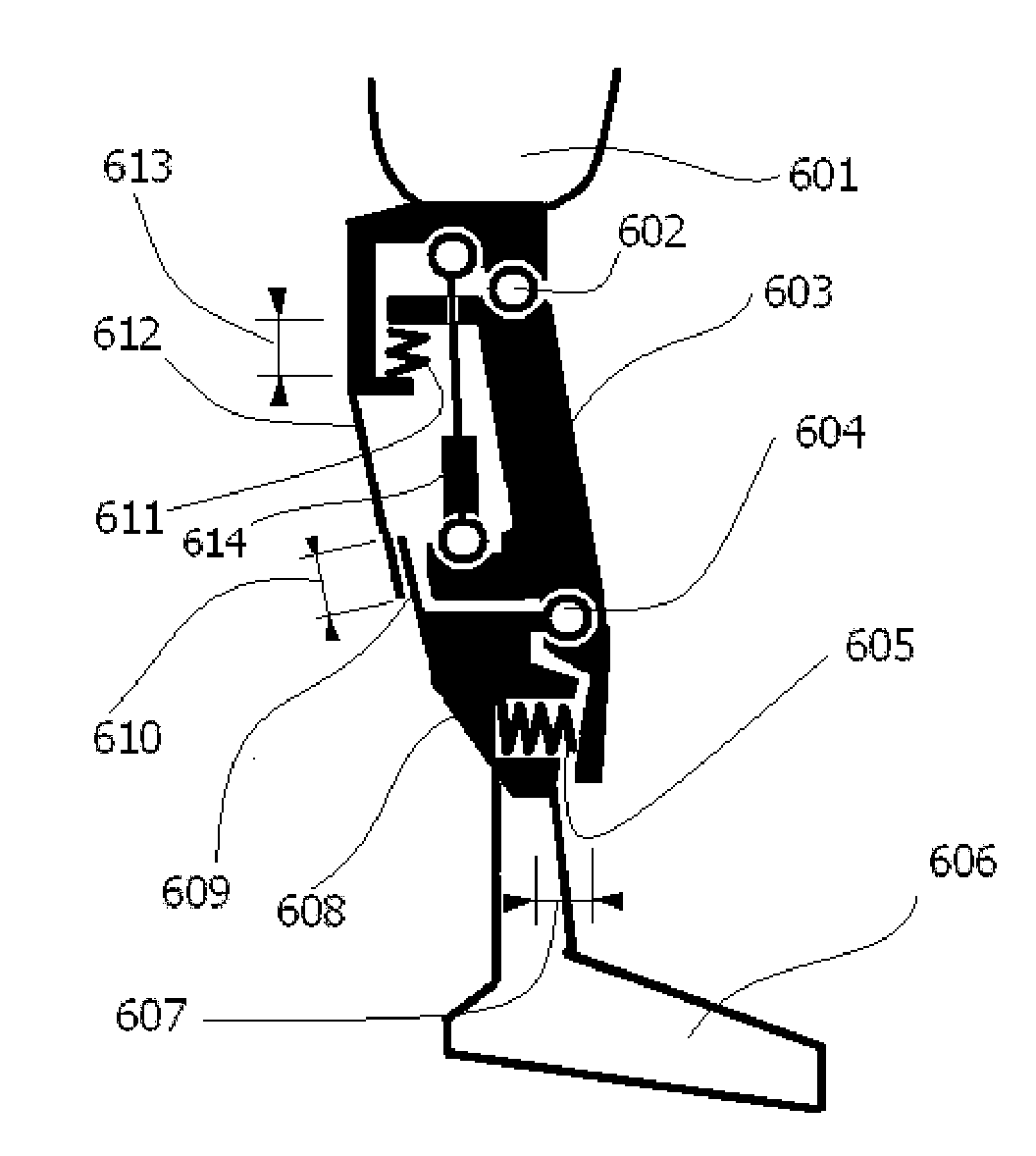
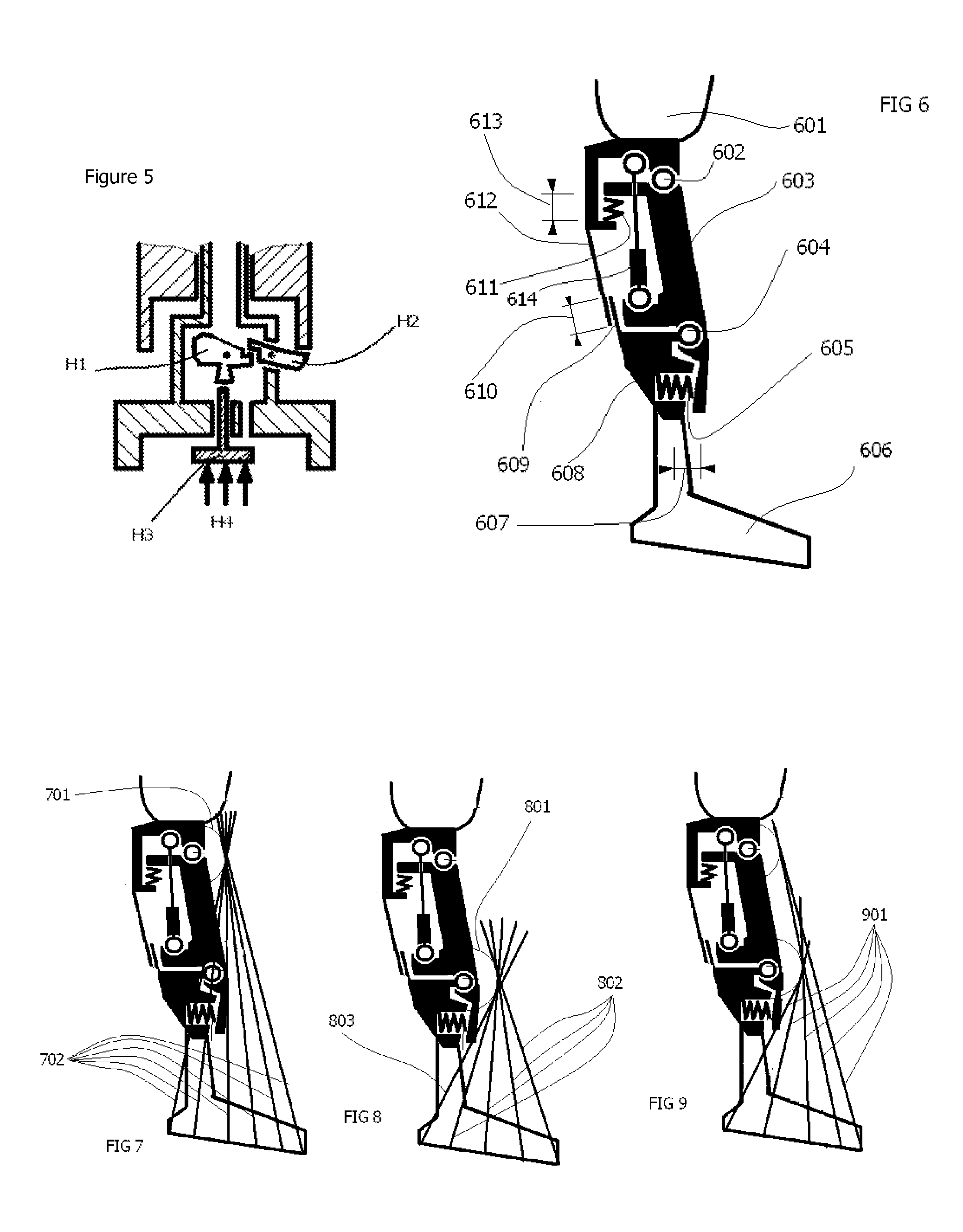
[0056]the invention is shown as in FIG. 6. In this figure, there is a stump attachment 601, a principal knee axis 602, a chassis 603, an auxiliary axis 604, a foot portion 606, a first resilient member 611, a second resilient member 605, a member 608 fixed to the foot portion pivotally linked to chassis 603. Thus movement by extension is resisted by resilient member 605, and the resilient member 605 allows a range of movement 607 that is input to the corresponding total displacement 610. Further input into total displacement 610 arises from the deflection of resilient member 611 when the chassis pivotally extends about pivot 602 relative to 601. By the use of suitable materials, it will be apparent to the man skilled in the art that a degree of inherent resilience of the chassis may provide a sufficient degree of resilience whereby the specific use of first and second resilient members is not necessary.

[0057]The device is manufactured such that when there is only one input signal—of...

second embodiment

[0068]The second embodiment as shown in FIG. 10, comprises a hydraulic solution wherein a valve 1001 / 1002 is disposed in controller 614 which valve, in an open state, permits a low resistance state of the controller. The reference numerals of his Figure correspond with those of FIGS. 6-9. Two valve bodies are constructed such that the valve is closed when these bodies meet and the valve is open if the valve bodies are parted. The valve is constructed such that with a minimum input 613 the top valve body is raised, and with a minimum of input 607 the lower valve body is drawn down. Due to the fact that valve body 1001 can be raised up by member 612 against resistance of resilient member 611, and valve body 1002 can be pulled down by member 606 / 608 a gap 610 can form.

[0069]Accordingly, signal 613 is produced in such a way that member 612 can produce the signal by over extending the knee joint, but cannot remove be removed solely upon flexion of the knee joint. Head 1006 can therefore ...


PUM


Abstract

The present invention relates to artificial limbs generally and joints for same. The present invention provides hydraulic functional units whereby enabling movement of artificial joints to closely correspond with natural human movement. In the provision of realistic joints, as used in prosthetic limbs, an important aspect in achieving realistic movement is providing a different operating characteristic to the joint when under load. One important characteristic of an artificial leg for achieving a natural-looking walking gait corresponding with those of a stabilised knee, i.e. a knee resisting flexion when under load, is when it bears at least some of the weight of the amputee. Properties of resilient mechanical members are utilized to enable a hydro-mechanical system to be controlled so that it releases a low joint resistance mode relative to a default high resistance mode. The invention also permits alternative embodiments such as electronic, electro fluidic or electromechanical means.

Description

CROSS-REFERENCE TO RELATED APPLICATIONS[0001]The present invention claims priority to international application serial number GB1101097.2, with the same title, filed on Jan. 11, 2011. The disclosure of the above-referenced patent application is hereby incorporated by reference in its entirety.FIELD OF THE INVENTION[0002]The present invention relates to artificial limbs generally and to joints for the same. In particular, the present invention relates to hydraulic functional units, generally classified as damping devices as connected between artificial limbs whereby to enable movement of artificial joints to closely correspond with natural human movement. More particularly, the present invention relates to systems operable to reduce or eliminate inadvertent collapse of external limb prostheses, to enable movement of artificial joints to closely correspond with natural human movement.BACKGROUND[0003]In the provision of realistic joints, as used in prosthetic limbs, an important aspect...

Claims


Application Information

Patent Timeline
IPC IPC(8): A61F2/64
CPCA61F2/64A61F2/6607A61F2/68A61F2002/7645A61F2002/745A61F2002/748A61F2002/7625A61F2002/5006A61F2/74A61F2/748A61F2002/5003A61F2002/5033A61F2002/5038A61F2002/6818A61F2002/6854
Inventor BOENDER, JACOB QUINTUS LAURENS ANTHONY
Owner BOENDER JENNIFER
Why Eureka
Try Eureka