Control of underwater turbine

a technology of underwater turbines and control towers, which is applied in the direction of instruments, renewable energy generation, greenhouse gas reduction, etc., can solve the problems of increasing the flow in undesirable fashion, uncontrollable flow, and many known systems for generating power from water flows, so as to reduce interference drag and increase the flow velocity of liquid. the effect of speed

Inactive Publication Date: 2012-07-26
ATLANTIS RESOURCES CORP PTE LTD
View PDF4 Cites 13 Cited by
  • Summary
  • Abstract
  • Description
  • Claims
  • Application Information

AI Technical Summary

Benefits of technology

[0055]Preferably a boot or a plug is provided at the blade root to cover any gaps or bumps or bolt heads and the like to minimise interference drag in that region.
[0056]Preferably, the housing defines a flow channel having a flow restriction from an opening forward of the rotor to a narrower throat adjacent the turbine body. Advantageously, this arrangement increases the velocity of liquid flowing through the flow channel in a restricted part of the flow channel, relative to an unrestricted part of the flow channel. The flow restriction preferably comprises a venturi, which may form part or the entire flow channel. In particular, the venturi may comprise a divergent-convergent-divergent venturi, tapering from openings at either end of the flow channel towards an inner part of the flow channel.

Problems solved by technology

However, many known systems for generating power from water flows are not easily controlled.
Also, there are times when flows change in an unpredictable manner, such as from some frontal, lunar or other kind of unforeseen event.
This can increase the water flow in an undesirable fashion, either in terms of a variation in frequency and / or amplitude, with the result being efficiency or componentry being negatively affected.
Furthermore, water environments include unpredictable elements such as large and small marine life, dirt, silt, growths, and other complicating factors.
Control systems to date have not been able to deal with these kind of output risk factors.

Method used


Image

  • Control of underwater turbine
  • Control of underwater turbine
  • Control of underwater turbine

Examples


Embodiment Construction

[0101]Underwater power generation systems typically contain a turbine having a number of blades or foils. The system also usually includes a power extraction device such as a generator or pump to generate power and rotation or movement of the blades or the foils under the influence of water pressure or lift causes power to be generated through the power extraction device. In its simplest form, rate of movement or rotation of the turbine is proportional to the movement or flow rate of the water that passes over or through the turbine. If the flow rate is too low, then the turbine will not function and no power is generated. Similarly, if the flow rate is irregular or inconsistent, the rate of power generation will also be irregular or inconsistent.

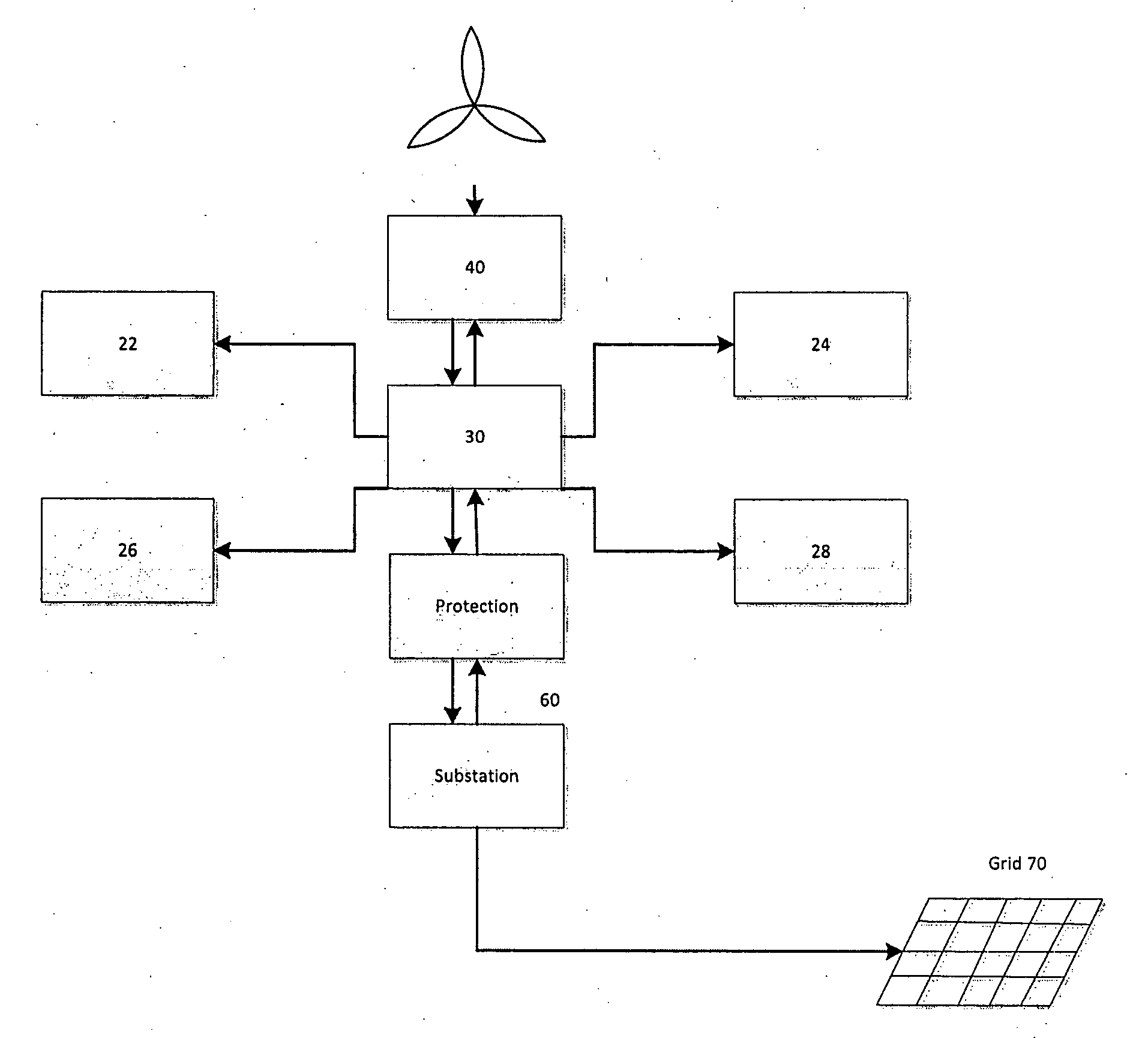
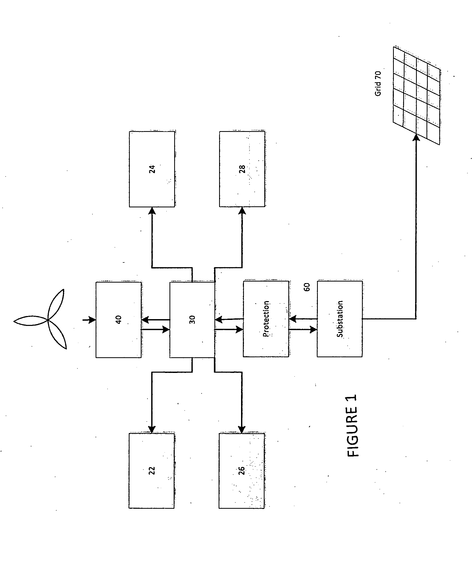
[0102]An example of the system for controlling operation of a water turbine according to a preferred embodiment of the present invention is set out in FIG. 1. Underwater power generator 40 is connected to power grid 70 and is capable of gen...


PUM


Abstract

A system and a method for controlling operation of an underwater power generator is described, as well as computing componentry for controlling the operation of the underwater power generator. The system comprises: meters for measuring selected properties associated with blade speed and inward water flow of the underwater power generator; a drive for altering one or more selected aspects of operation of the underwater power generator; and a data processing apparatus comprising a central processing unit (CPU), a memory operatively connected to the CPU, the memory containing a program adapted to be executed by the CPU, wherein the CPU and/or memory are operatively adapted to receive information from the meters to calculate a Tip Speed Ratio (TSR or λ) and implement an instruction to the drive to change the one or more selected operating parameters of the underwater power generator in response to the calculated TSR or λ.

Description

FIELD OF THE INVENTION[0001]The invention relates generally to systems and methods suitable for controlling operation of underwater power generation units.BACKGROUND TO THE INVENTION[0002]It is known to generate power from flows of water. However, many known systems for generating power from water flows are not easily controlled. In order to connect to an electricity grid and supply power thereto, it is useful to have predictable and controllable power outputs.[0003]Although the flows of water at particular locations generally vary in a predictable manner, usually as tides ebb and flow, these variations change the power which can be extracted from underwater power generation units and the efficiency with which the power is extracted when some components are not infinitely variable or at all in certain ways. Also, there are times when flows change in an unpredictable manner, such as from some frontal, lunar or other kind of unforeseen event. This can increase the water flow in an und...

Claims


Application Information

Patent Timeline
Patent Type & Authority Applications(United States)
IPC IPC(8): G06F1/26F03B13/10
CPCF03B15/08Y02E10/226F03B15/12F05B2270/335F05B2270/1014F05B2270/327F05B2270/329F03B15/16Y02E10/20F03B13/10F03B15/00
Inventor KEIR, JOHN
Owner ATLANTIS RESOURCES CORP PTE LTD
Why Eureka
Try Eureka