Cutting tool inserts

a technology of cutting tool and insert, which is applied in the direction of earthwork drilling, well accessories, drilling/welling, etc., can solve the problems of affecting the cutting accuracy of the cutting tool, the cutting insert and the blade etc. on which they are mounted wear rapidly, and the potential for problems such as the inability to remove the cuttings

Inactive Publication Date: 2012-08-02
RUSSELL MARK +1
View PDF4 Cites 13 Cited by
  • Summary
  • Abstract
  • Description
  • Claims
  • Application Information

AI Technical Summary

Benefits of technology

[0022]The degree of spiral may be sufficiently limited, and the degree of taper sufficiently large, and the angular separation of a ridge and trough in the radial plane of the axis is, such that the insert is not required to rotate on ejection from the die. In this event, ejection is, of course, in the axial direction. Other directions are feasible, for example in the direction of taper of the ridges.

Problems solved by technology

Firstly, the milling of casing and packers by machining them is abrasive to the tool.
The cutting inserts and blades etc on which they are mounted wear away rapidly in the aggressive environment.
Secondly, there is no requirement for great precision—the application is generally just the removal of a well casing, and not precision machining.
Such long shavings run the risk that they bundle together in a “bird's nest”, making removal of the cuttings potentially problematic.
However, while the tool is ideal, it is time-consuming, and thus expensive, to construct.
Consequently, despite the obvious cost savings to be had by this arrangement, the cutting and wear resistant performance is certainly compromised.
Any given insert is unlikely to present a clean cutting edge, and if it does, long shavings of the work piece may result.
Consequently, while inexpensive, this arrangement does not perform as well as the first arrangement described above.
The availability of shapes is of course limited, to some extent, by the process by which inserts are routinely made.

Method used


Image

  • Cutting tool inserts
  • Cutting tool inserts
  • Cutting tool inserts

Examples


Embodiment Construction

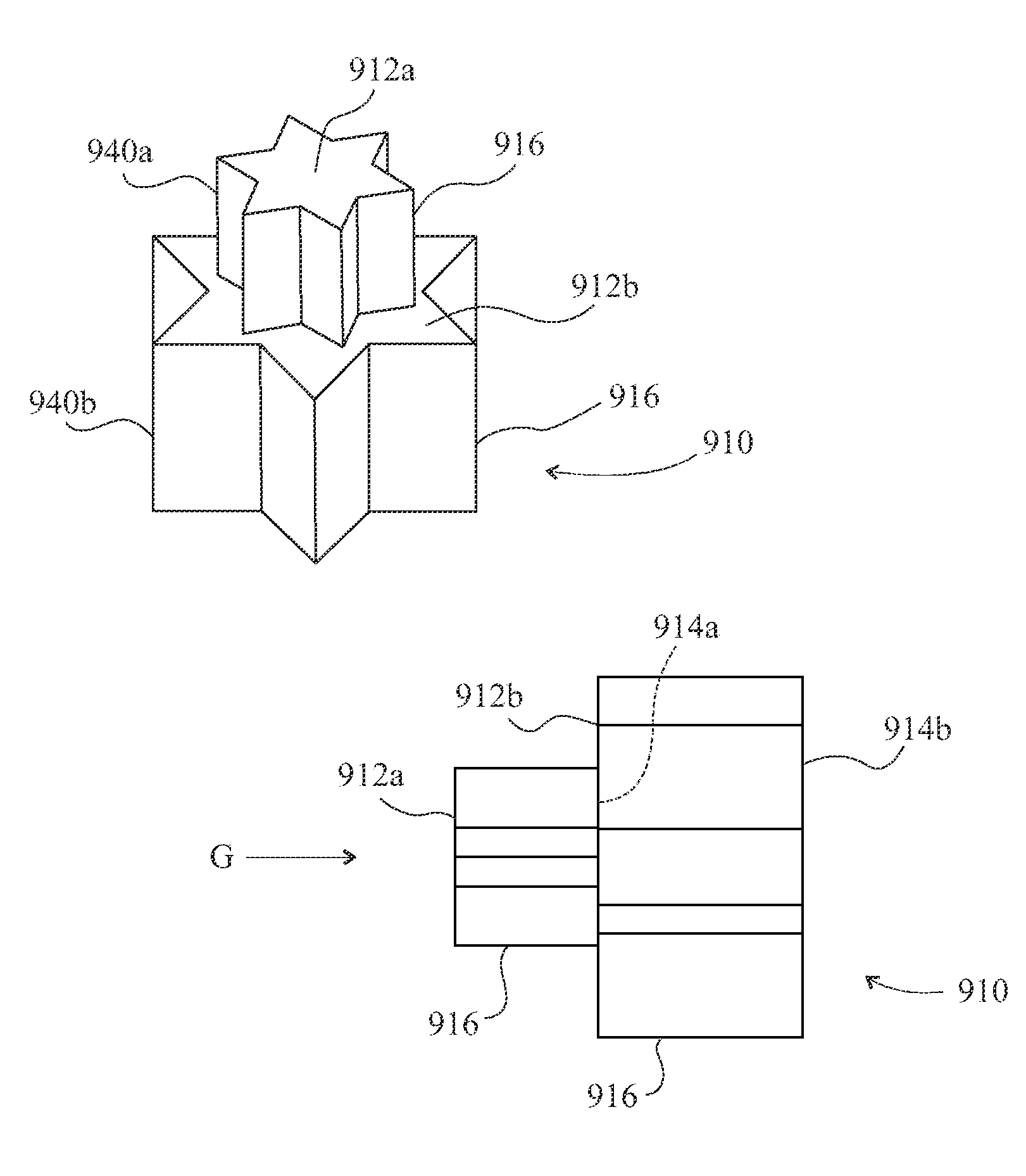
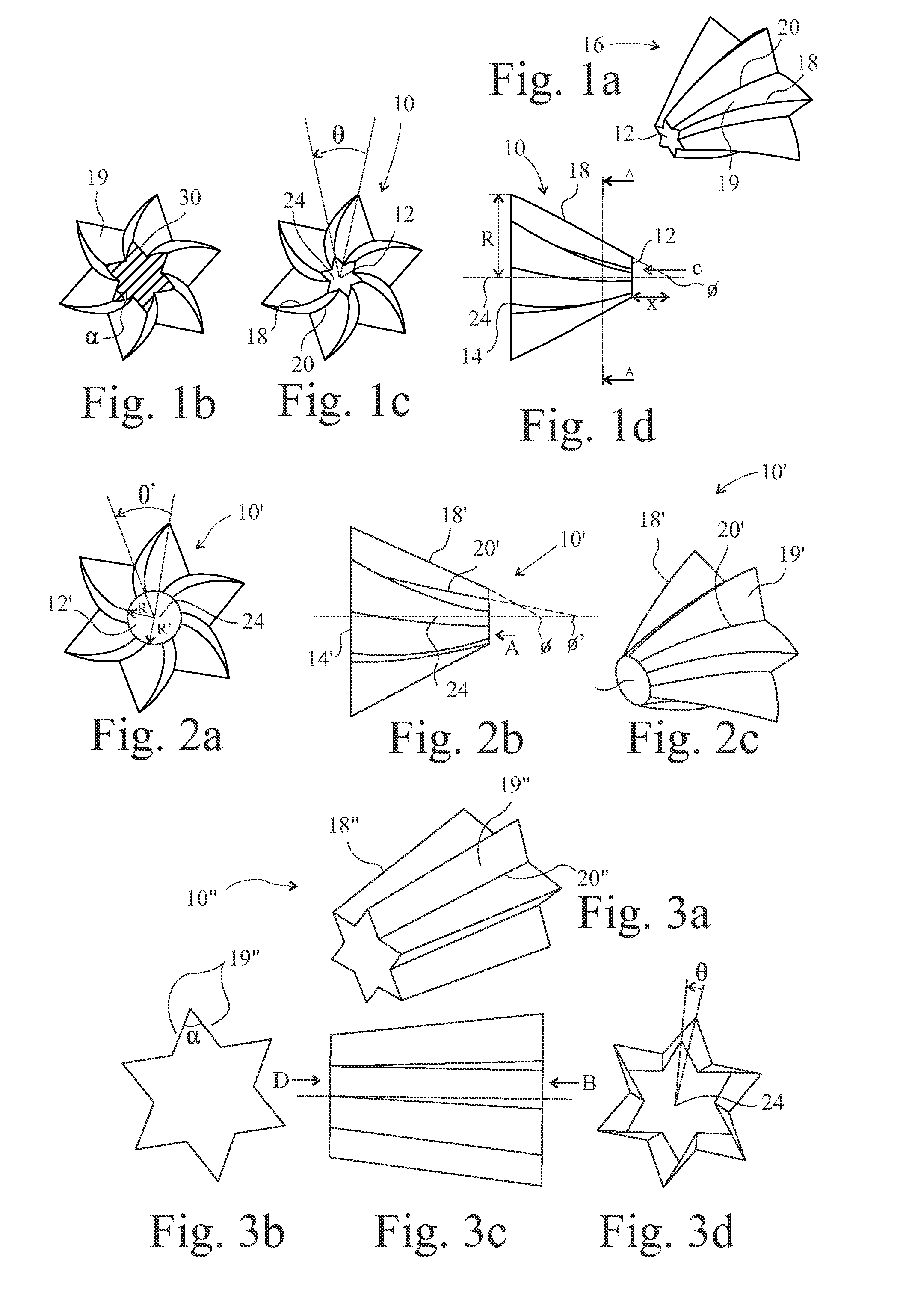
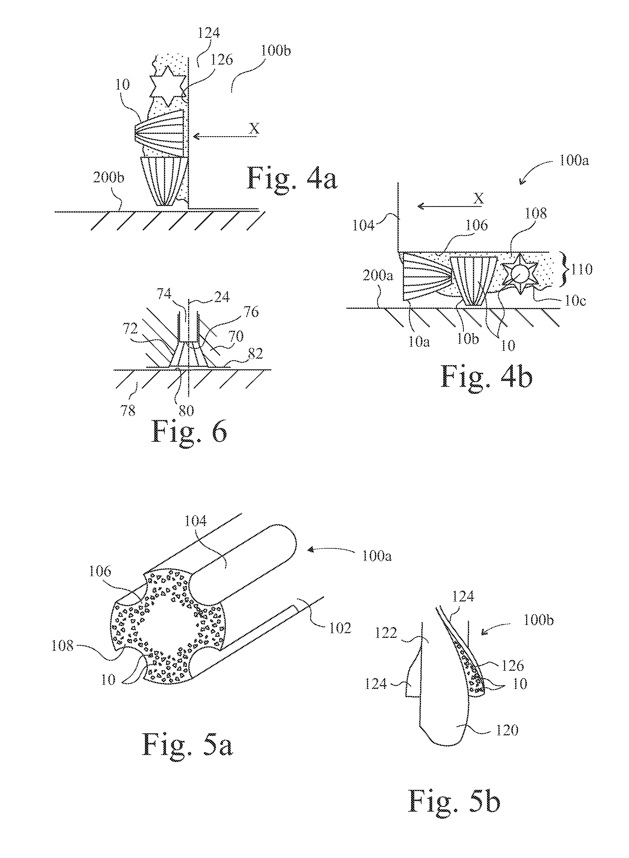
[0044]Referring now to FIG. 1, an insert 10 is illustrated comprising end faces 12 and 14, and flanks 16 consisting of ridges 18 separated by troughs 20, forming faces 19 between them. The insert 10 has an axis 24 extending between the end faces 12,14, which are shown as being flat faces perpendicular to the axis 24, although either face may be concaved, convex or faceted, internally or externally, or inclined with respect to the axis 24. A section taken perpendicular to the axis 24, such as the section A-A, has a regular six pointed star shape profile 30 that is the same from the small end 12 to the large end 14. The angle between faces 19 is α, which typically is 60°. However, the ridges 18, and corresponding troughs 20, spiral about the axis 24 between the ends 14 and 12. Thus, the ridges both taper and spiral between the ends 12,14.

[0045]The degree of taper is, in the case of FIG. 1, non-linear. That is to say, the radial distance R of the ridge 18 from the axis 24 decreases at ...


PUM


Abstract

An insert (10) for a cutting tool (100) for use down a well bore comprises a body of a hard material (tungsten carbide) suitable for cutting steel. The body is shaped for formation in a mould that comprises a die (70) and first (74) and second (78) punches and arranged so that the first punch can eject the body after formation from an opening of the die closed during formation by said second punch. The insert has first (12) and second (14) ends whose faces are defined, at least in part, by corresponding faces of the first and second punch. Between them is a longitudinal axis (24) of the insert. The area of the first end is less than the area of the second end. The body has flanks (16) that form ridges (18) extending between the first and second ends. The ridges form cutting edges of the insert. They are separated by V-shaped troughs (20) of said flanks. The ridges taper and spiral about the axis.

Description

[0001]This invention relates to cutting tool inserts, in particular to random distribution inserts for use on cutting tools adapted to remove casings from well bores.BACKGROUND[0002]Down hole mills are known for removing casing, packers and other debris down hole for the purpose of renovating the hole. Such tools are also referred to as fishing tools and may comprise a cylindrical body adapted to be rotated about their longitudinal axis having cutting faces either arranged on the face of peripheral blades, in which event, the face is perpendicular to the cutting action (that is, parallel to, or possibly helically inclined to, the axis of rotation of the tool) or on an end face of the tool, in which event, the face is substantially parallel to the cutting action (for example, lying on a radial plane of the axis of rotation of the tool).[0003]In either case, the body of the tool is protected by cutting elements fixed thereto that are made of a material (usually tungsten carbide compos...

Claims


Application Information

Patent Timeline
Patent Type & Authority Applications(United States)
IPC IPC(8): E21B10/36
CPCE21B10/56E21B10/567E21B29/002E21B10/627E21B10/633E21B10/5673E21B10/00
Inventor RUSSELL, MARKOLLERENSHAW, ANDY
Owner RUSSELL MARK
Why Eureka
Try Eureka