Method and system for carrying out photoplethysmography

a technology of photoplethysmography and plethysmography, which is applied in the field of photoplethysmography, can solve the problems of difficult retrieval of the photoplethysmographic signal of interest, and achieve the effect of increasing the likelihood

Active Publication Date: 2012-08-02
KONINKLIJKE PHILIPS ELECTRONICS NV
View PDF12 Cites 62 Cited by
  • Summary
  • Abstract
  • Description
  • Claims
  • Application Information

AI Technical Summary

Benefits of technology

[0004]It is desirable to provide a method and system of the types mentioned above that increase the likelihood of being able to retrieve a relatively clear biometric signal even where there is noise in the green channel.
[0008]Thus, the method makes use of a channel sensitive to variations in reflected and / or transmitted light due to pulsating blood plasma flow. The signal in this channel can be used in addition to or as an alternative to a channel sensitive to variations in the amount of oxyhemoglobin in the illuminated area. Because a different frequency of light is used, there is a greater likelihood that a stronger signal will be obtained in circumstances in which there is noise in a green channel.
[0012]This embodiment has the effect that it is possible to use photosensors (including arrays of photodiodes) implemented in silicon technology. Such sensors generally show a peak in their sensitivity around 800 nm or 900 nm. At 1000 nm, the sensitivity is slightly lower, but still high enough to detect photons in this spectral range, in which there are also favorable peaks in the absorption spectrum of water, in particular at 970 nm. There are many commercially available and cheap silicon-based sensors, e.g. CMOS and CCD arrays.
[0014]This embodiment has the effect of eliminating ambient light, including in particular also light with periodic components.
[0018]This makes the correction carried out using the signal from the second sensor more accurate, because the signals both include components representative of illumination changes or movements of the same surface area of the living subject. The splitting can be in the wavelength domain or it can be a polarization split.

Problems solved by technology

A problem of the known method is that the green channel may be subject to noise that makes it difficult to retrieve the photoplethysmographic signal of interest.

Method used


Image

  • Method and system for carrying out photoplethysmography
  • Method and system for carrying out photoplethysmography
  • Method and system for carrying out photoplethysmography

Examples


Embodiment Construction

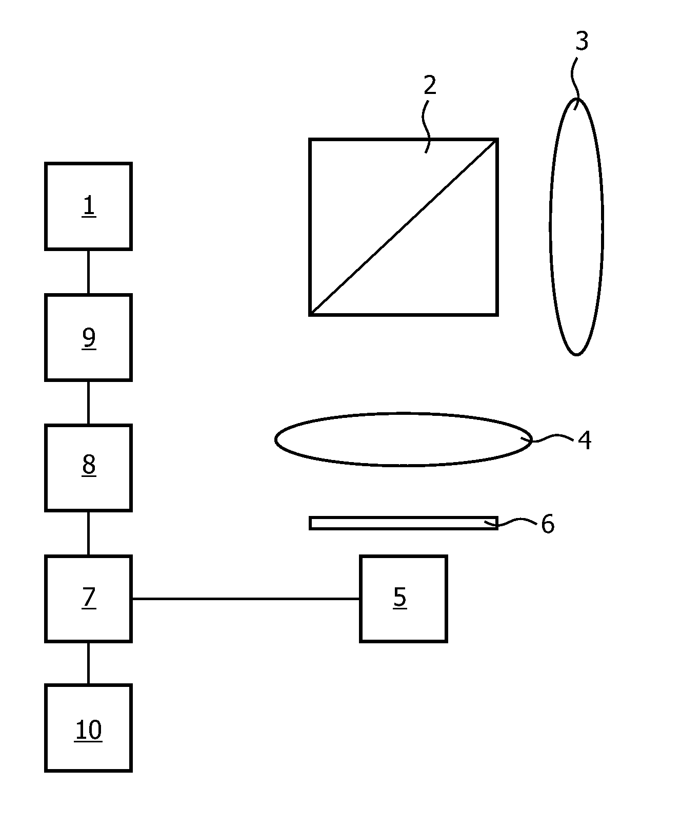
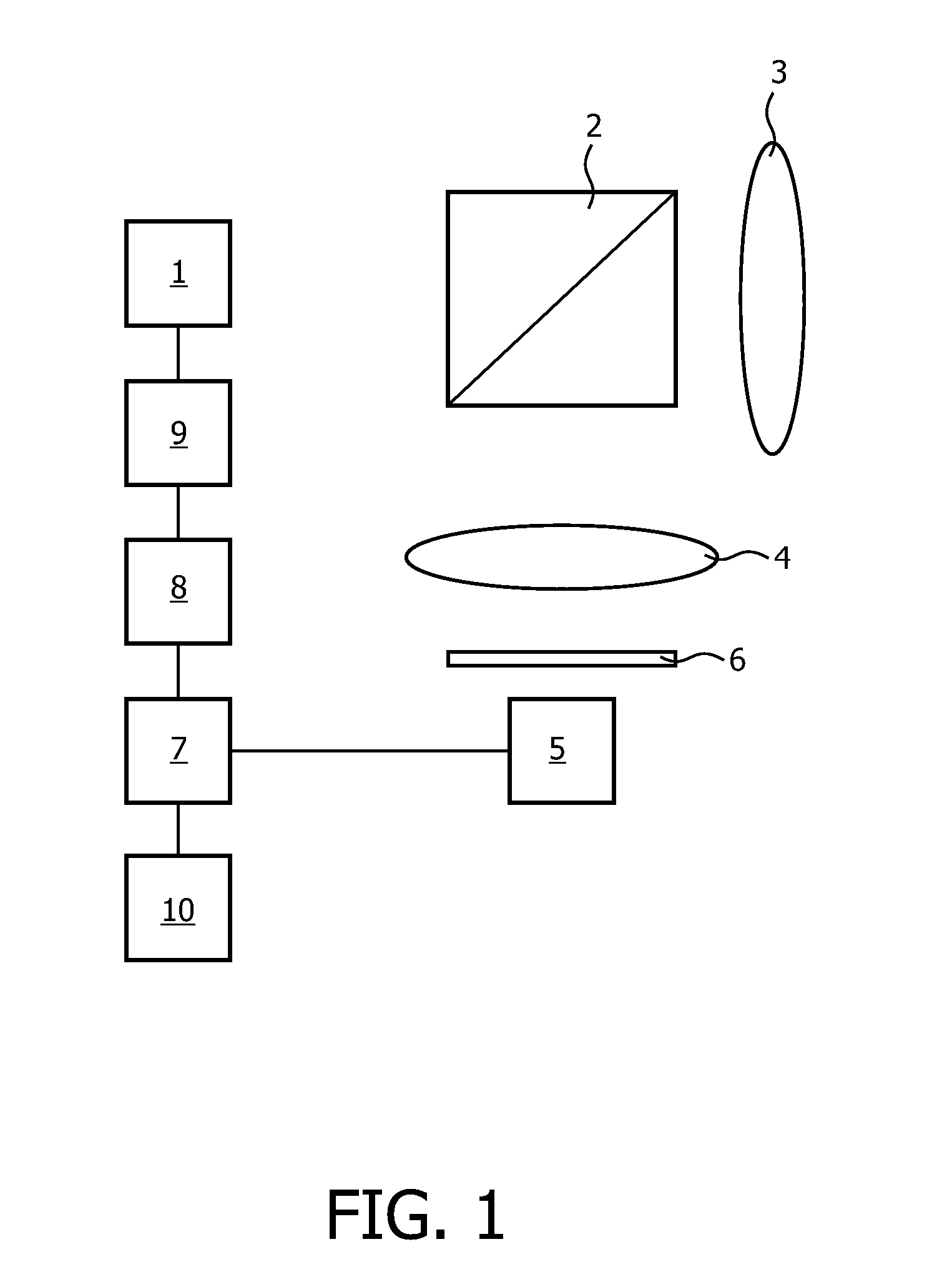
[0035]Several embodiments of a system for remote photoplethysmography will be explained herein. Photoplethysmography is a method for characterizing certain periodic physiological phenomena using skin reflectance variations. The human skin can be modeled as an object with at least two layers, one of those being the epidermis (a thin surface layer) and the other the dermis (a thicker layer underneath the epidermis). Approximately 5% of an incoming ray of light is reflected in the epidermis, which is the case for all wavelengths and skin colors. The remaining light is scattered and absorbed within the two skin layers in a phenomenon known as body reflectance (described in the Dichromatic Reflection Model). The epidermis behaves like an optical filter, mainly absorbing light. In the dermis, light is both scattered and absorbed. The absorption is dependent on the blood composition, so that the absorption is sensitive to blood flow variations. The optical properties of the dermis are gene...


PUM


Abstract

A method of photoplethysmography includes processing a signal (46;56) based on at least one signal (35;50) from at least one sensor (5;18-20;26;63) arranged to capture light from a living subject to extract information on a characteristic of a periodic biological phenomenon. At least one of the signals (35;50) from at least one sensor (5;18-20;26;63) is obtained by using at least one of a light sensor (1;11-13) and a filter (6;17;64) placed before the at least one sensor (5;18-20;26;63) tuned to a peak in an absorption spectrum of water.

Description

FIELD OF THE INVENTION[0001]The invention relates to a method of photoplethysmography, a system for carrying out photoplethysmography, and a computer program.FIELD OF THE INVENTION[0002]Verkruysse, W. et al., “Remote plethysmographic imaging using ambient light”, Optics Express 16 (26), 22 Dec. 2006, pp. 21434-21445 discloses a method in which photoplethysmographic signals were measured remotely using ambient light and a simple consumer-level digital camera in movie mode. Heart and respiration rates could be quantified up to several harmonics. Although the green channel featured the strongest photoplethysmographic signal, corresponding to an absorption peak by (oxy-)hemoglobin, the red and blue channels also contained photoplethysmographic information.[0003]A problem of the known method is that the green channel may be subject to noise that makes it difficult to retrieve the photoplethysmographic signal of interest. This is true to an even greater extent of the other channels, which...

Claims


Application Information

Patent Timeline
Patent Type & Authority Applications(United States)
IPC IPC(8): A61B5/02A61B6/00
CPCA61B5/02028A61B5/0261A61B5/02416A61B5/1455A61B5/7214
Inventor JEANNE, VINCENTCENNINI, GIOVANNIKIRENKO, IHOR OLEHOVYCH
Owner KONINKLIJKE PHILIPS ELECTRONICS NV
Why Eureka
Try Eureka