Supercharge Your Innovation With Domain-Expert AI Agents!

Manufacturing method of glass strip, glass strip, and glass substrate

a manufacturing method and glass technology, applied in glass tempering apparatus, manufacturing tools, glass making apparatus, etc., can solve the problems of unstable gas convection current generation within the heating furnace, long time and high manufacturing cost to execute all steps, and achieve high flatness of glass strips, reduce the adhesion of contamination, and increase cost

Inactive Publication Date: 2012-08-09
FURUKAWA ELECTRIC CO LTD
View PDF4 Cites 1 Cited by
  • Summary
  • Abstract
  • Description
  • Claims
  • Application Information

AI Technical Summary

Benefits of technology

The present invention provides a manufacturing method for a glass strip that ensures high flatness and reduces adhesion of contaminations to the glass strip after heating and drawing. The method includes heating and softening a glass plate preform, drawing the preform to a desired thickness, and forming gas flows on both surfaces of the preform that are equal to each other. The glass strip obtained using this method has a high flatness and low waviness, and can be easily lapped and polished. The invention also provides various methods for achieving these technical effects, such as controlling the pressure and temperature in the heating furnace, introducing gas to the surfaces of the glass plate preform, and using specific glass plate preforms.

Problems solved by technology

Since glass plates with higher accuracy are required in the future, it is estimated that the glass plate is polished three times. The conventional method has, therefore, problems in that many steps including grinding and polishing are required, and in that it takes long time and much manufacturing cost to execute all steps.
The conventional method has many steps and is poor in productivity.
However, even if the air curtain is disposed in the lower portion of the heating furnace to cut off mixture of the atmosphere from the lower portion thereof as explained in the method disclosed in the Patent Document 2, an unstable convection current of gas is still generated within the heating furnace.
Due to this, it is often impossible to suppress the waviness and a bending of the surface of the thin glass plate.
If the unstable convection current of gas is generated within the heating furnace due to the mixture of the atmosphere from the upper portion of the heating furnace, dust within the atmosphere enters the heating furnace and often adheres to the surface of the obtained thin glass plate.
The glass surface is evaporated while heating the glass plate, the evaporated gas is transformed into particles in a low temperature portion within the furnace, and the particles are deposited on the preform that is being drawn or the glass strip after the drawing, thereby causing a surface defect.
The evaporated gas corrodes and deteriorates a member within the furnace or reacts with the material within the furnace, thereby generating dust or glass dust.
The glass dust is deposited on the preform that is being drawn or the glass strip after the drawing, thereby causing a surface defect.

Method used


Image

  • Manufacturing method of glass strip, glass strip, and glass substrate
  • Manufacturing method of glass strip, glass strip, and glass substrate
  • Manufacturing method of glass strip, glass strip, and glass substrate

Examples


first embodiment

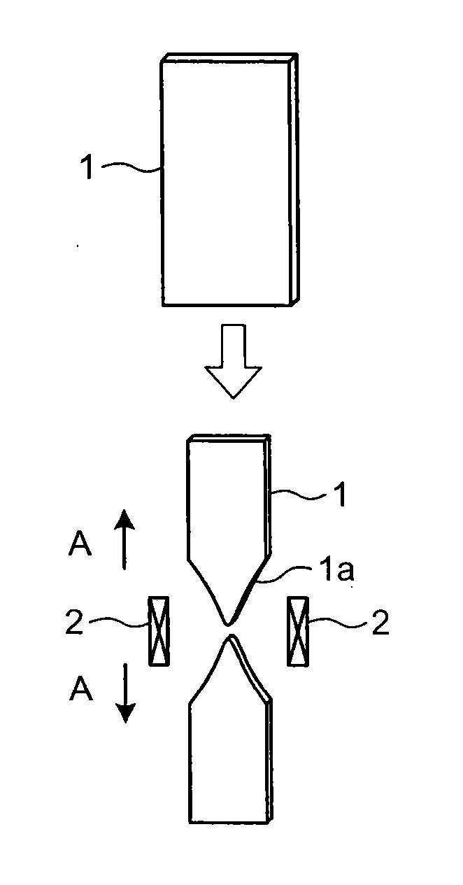
[0044]FIG. 1 is a schematic view of a peaked shape forming step in a manufacturing method of a glass strip according to the present invention. According to the first embodiment, a long plane glass plate preform 1 is used as a preform. A material for the glass plate preform 1 is quartz glass. To make the glass plate preform 1 have a surface state in which a thickness is constant and a flatness falls within a predetermined range (0.1 mm / 100 mm to 0.01 mm / 100 mm), the glass plate preform 1 is ground from both surfaces thereof. Thereafter, the glass plate preform 1 is subjected to flame polishing or mechanical polishing until it becomes substantially transparent. To prevent cracking, corners of the glass plate preform 1 are chamfered to 0.5 mm radius or more. A glass plate preform having a length of about 1 meter, a width of 350.5 mm, a thickness of 10.8 mm, and a surface roughness Ra of 0.05 micrometer is used. A cross-sectional aspect ratio of the glass plate preform 1 is 32.45. At th...

second embodiment

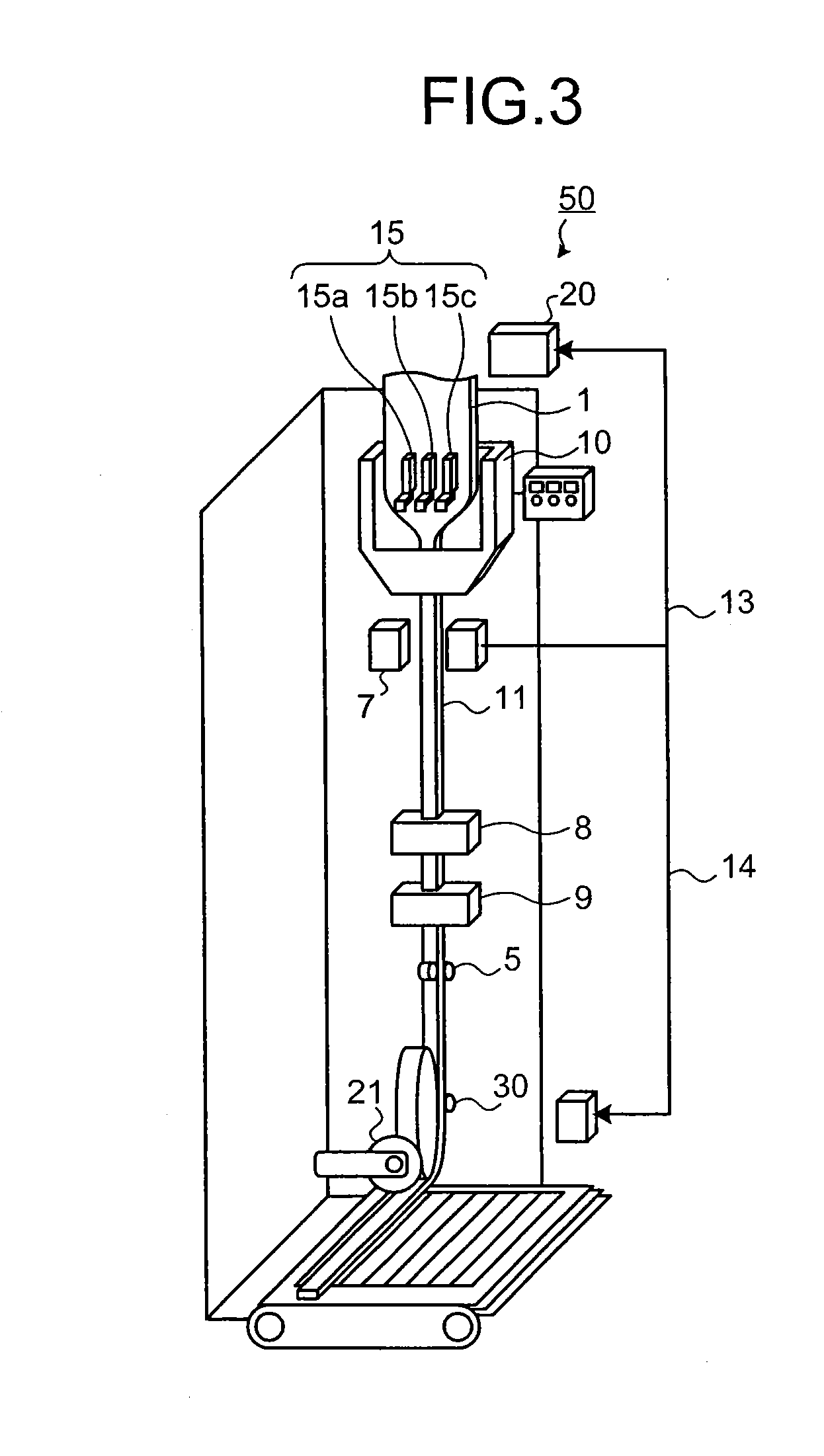
[0066]According to a second embodiment, at a heating and drawing process, nitrogen gas is introduced into the heating furnace 10 and surfaces of the glass strip 11 are doped with nitrogen to improve rigidity of the surfaces thereof. In addition, right after the heating and drawing process, the glass strip 11 is caused to pass through an ammonium gas atmosphere and the surfaces of the glass strip 11 are doped with nitrogen to improve the rigidity of the surfaces thereof. Similarly to the first embodiment, gas is introduced to the both surfaces of the glass plate preform 1 independently of each other, the internal pressure of the heating furnace 10 is kept positive relative to the atmospheric pressure, and the gas flows introduced to the both surfaces of the glass plate preform 1 are made equal to each other.

[0067]By thus improving the rigidity of the surface of the glass strip 11, it is possible to prevent the surface of the glass strip 11 from being damaged by the guide roll 5 or th...

first example

[0073]A glass plate preform having a width of 100 mm and a thickness of 2 mm is used. A surface roughness Ra of the glass plate preform is 73 nm. The glass plate preform is drawn by a heating furnace by the manufacturing method according to the present invention. As a result, a glass plate having a width of 22.3 mm and a thickness of 0.45 mm is obtained. A drawdown rate is 20%. Finally, a glass strip having a flatness of 1 μm / mm, a waviness of 9 nm, and an average roughness Ra of 10 nm is manufactured.


PUM

PropertyMeasurementUnit
viscosityaaaaaaaaaa
viscosityaaaaaaaaaa
viscosityaaaaaaaaaa

Abstract

A manufacturing method of a glass strip, the method including a heating and drawing process of heating and softening a glass plate preform, drawing the glass plate preform to have a desired thickness, and forming a glass strip, wherein at the heating and drawing process, the glass plate preform is drawn so that an internal pressure of a heating furnace is kept positive relative to an atmospheric pressure and so that gas flows introduced to both surfaces of the glass plate preform, respectively are equal to each other within the heating furnace.

Description

CROSS REFERENCE TO RELATED APPLICATION[0001]The present application is a divisional of U.S. application Ser. No. 11 / 722,964, filed on Jun. 27, 2007, which was the National Stage of International Application No. PCT / JP2005 / 019320, filed on Oct. 20, 2005, which claims the benefit of provisional Application No. 60 / 669,905, filed on Apr. 11, 2005 and claims priority to Japanese Application No. 2004-378004, filed on Dec. 27, 2004. Application Ser. No. 11 / 722,964 is hereby incorporated by reference in its entirety.BACKGROUND OF THE INVENTION[0002]1. Field of the Invention[0003]The present invention relates to a manufacturing method of a thin bar-like glass strip by heating and drawing a thick plate-like glass plate preform, a glass strip manufactured by this manufacturing method, and a glass substrate.[0004]2. Description of the Related Art[0005]An improvement in a flatness and an improvement in a surface roughness are most important factors for glass plates used as a substrate of a semic...

Claims


Application Information

Patent Timeline
Patent Type & Authority Applications(United States)
IPC IPC(8): C03B23/037C03B20/00
CPCC03B21/02C03B29/16C03B23/037
Inventor NAKAMURA, TOSHIHIROKUMADA, TETSUYANAKA, YASUHIRO
Owner FURUKAWA ELECTRIC CO LTD
Features
  • R&D
  • Intellectual Property
  • Life Sciences
  • Materials
  • Tech Scout
  • Unparalleled Data Quality
  • Higher Quality Content
  • 60% Fewer Hallucinations
Learn More