Tank for storing and withdrawing hydrogen and/or heat

a technology for hydrogen storage and heat storage, applied in chemical/physical/physical-chemical processes, mechanical equipment, chemical apparatuses and processes, etc., can solve the problems of high production cost, require external thermal energy source, and facilitate self-contained storage tanks to be produced, so as to improve heat exchange with heat storage elements, reduce production cost, and facilitate the effect of handling

Inactive Publication Date: 2012-08-09
MCPHY ENERGY +1
View PDF3 Cites 27 Cited by
  • Summary
  • Abstract
  • Description
  • Claims
  • Application Information

AI Technical Summary

Benefits of technology

[0036]Advantageously, the hydrogen storage material consists of a pellet of hydrides compacted so as to form a solid block. This solution enables the heat exchanges with the heat storage elements to be improved with respect to the solutions of the prior art implementing powdered materials, and the commercial production of the tank to be simplified. Indeed, the powdered materials are dangerous to handle due to their pyrophoric nature. The solution according to this alternative enables solid pellets, in particular with a discoid or toric or prismatic shape, which can be safely handled, to be produced.
[0037]This device has the major advantage of enabling the exchange of heat on both faces of the pellets even though, in the system of the prior art, the exchange could occur only radially.
[0038]With this arrangement, it is possible to adjust the pressure in the capsule and to have a very low residual volume with maximum contact between the heat storage material and the capsule walls, and therefore with the hydride facing it. Owing to this invention, it is possible to arrange the basic hydride tanks horizontally, and the entire assembly can be moved without any problem.

Problems solved by technology

These different solutions have the disadvantage of requiring an external thermal energy source.
These solutions therefore do not enable self-contained storage tanks to be produced, and they have high production costs.
These disadvantages are even more detrimental when the hydrogen storage materials are of the magnesium hydride type, with a high operating temperature, on the order of 300° C. and with a reaction enthalpy greater than 36 million joules (more than 10 kilowatt-hours) per kilogram of stored hydrogen.
The solutions proposed by the prior art patents are therefore unsuitable for such reaction heats.
The solution described in patent FR 2924787 has another disadvantage: the tubes “bathe” in the phase change material (heat storage material), and are therefore necessarily vertical, resulting in bulk.
This means that there is a limited hydrogen storage volume when satisfactory filling and withdrawal speeds are desired.
Indeed, the interactions with the gaseous hydrogen and the porous material reacting by hydriding / dehydriding are relatively low due to a low exchange surface.

Method used


Image

  • Tank for storing and withdrawing hydrogen and/or heat
  • Tank for storing and withdrawing hydrogen and/or heat
  • Tank for storing and withdrawing hydrogen and/or heat

Examples


Embodiment Construction

[0063]The invention can be better understood in view of the following description, which refers to the appended drawings relating to non-limiting examples of embodiments of the invention.

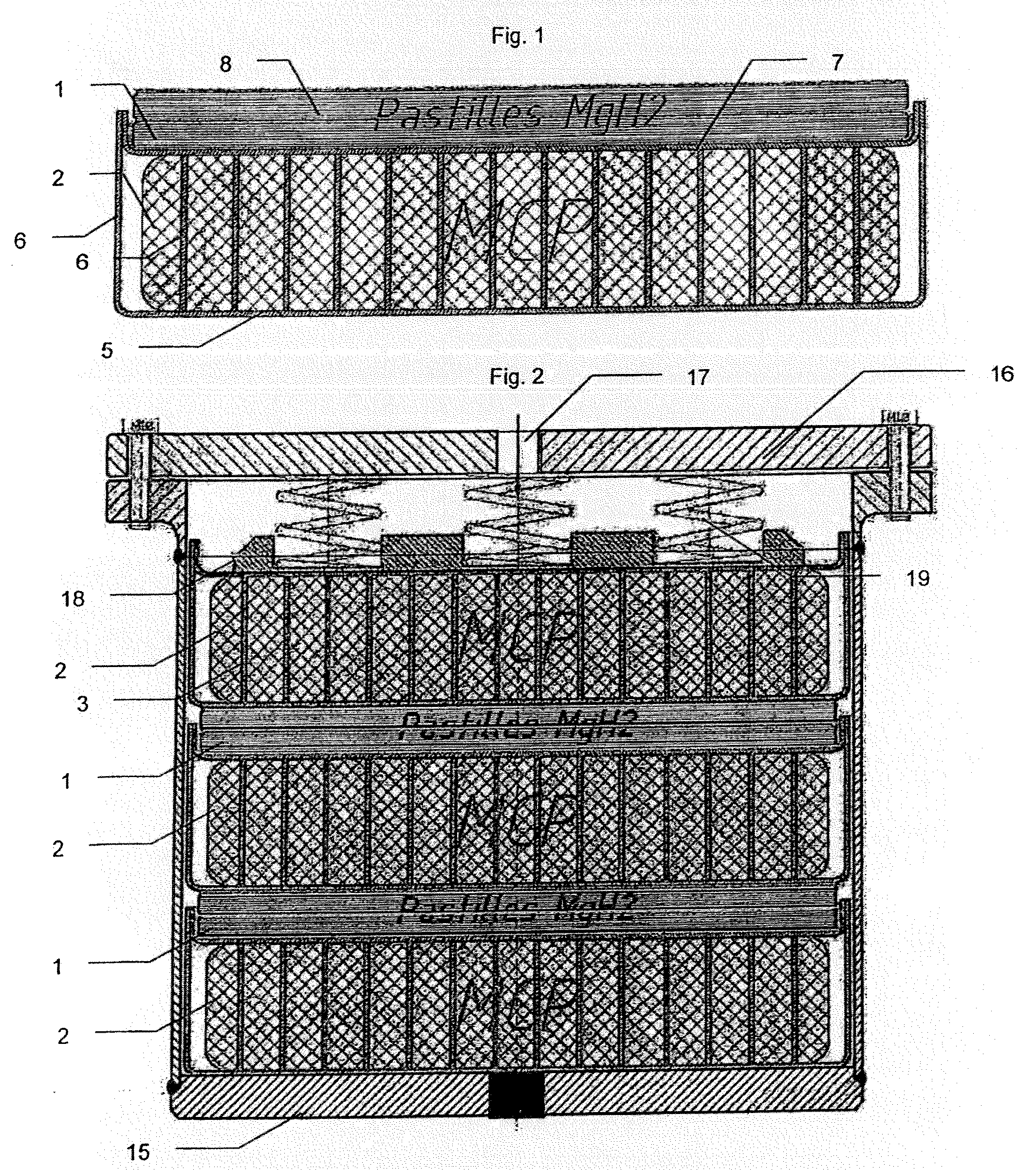
[0064]FIG. 1 shows a first example of an embodiment of a basic storage module for implementing the invention.

[0065]FIG. 2 shows a cartridge including a plurality of hydride pellets and heat storage material capsules.

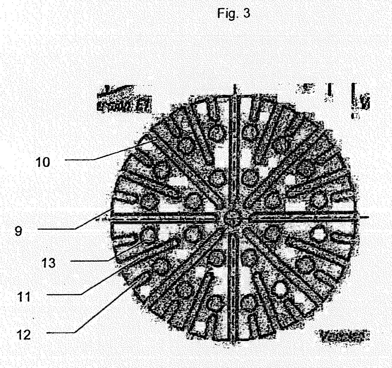
[0066]FIG. 3 shows an example of a diffuser.

[0067]FIGS. 4 and 5 show a longitudinal and transverse cross-section view of a tank including a plurality of cartridges.

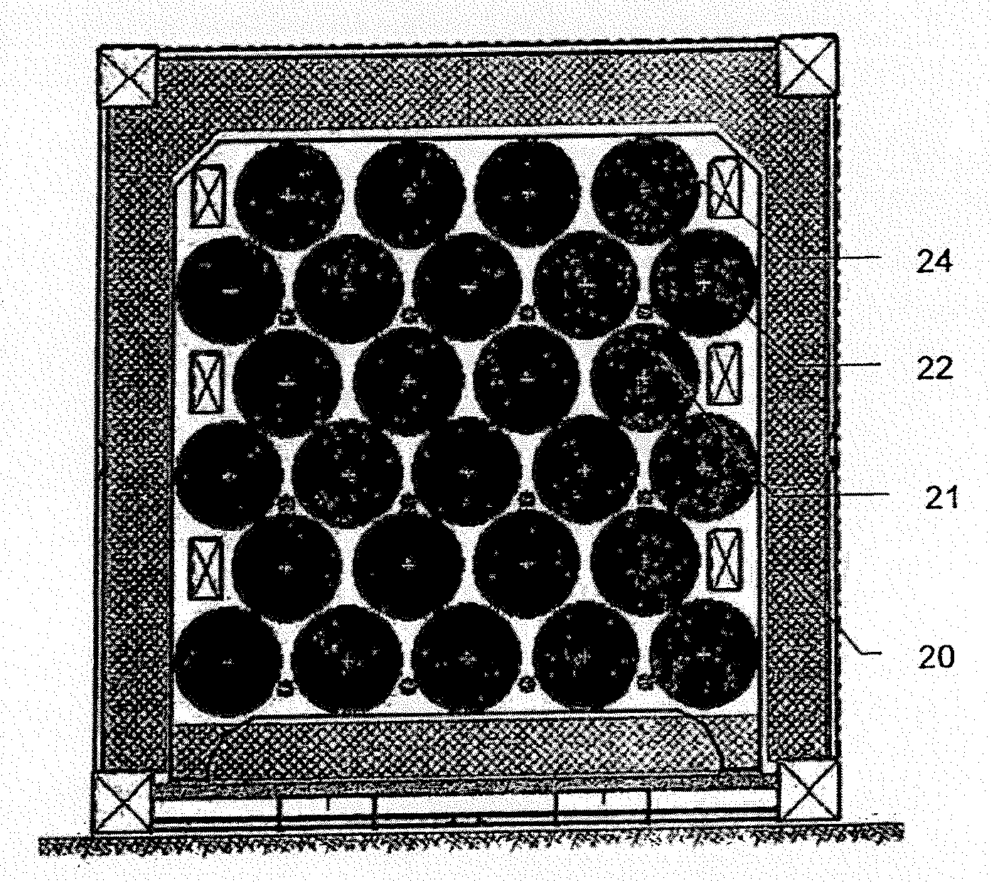
[0068]FIGS. 6 and 7 show cross-section views, respectively of a cartridge and of a basic module according to a second alternative embodiment.

[0069]FIG. 8 shows another alternative of such a cartridge.

[0070]FIGS. 9 and 10 show another alternative implementing one and three diffusers, respectively.

[0071]FIG. 1 shows a cross-section view of a basic hydrogen storage module, for implementing a storage tank according to the inventio...


PUM


Abstract

The present invention relates to a tank for storing and withdrawing hydrogen by means of a reversible hydriding/dehydriding reaction, said tank consisting of a thermally insulated chamber that includes a plurality of elements (2) for storing hydrogen in the form of hydrides, each element having at least one surface for exchange with the gaseous hydrogen and at least one heat exchange surface, characterized in that it further comprises a plurality of heat storage elements (3) for preserving and releasing the heat that is associated with the reversible hydriding/dehydriding reaction.

Description

FIELD OF THE INVENTION[0001]This invention relates to the field of storing and releasing hydrogen, implementing porous elements interacting with hydrogen so as to reversibly form metal hydrides.[0002]The hydriding / dehydriding reaction, for example of magnesium, is dependent on temperature. The hydriding reaction is exothermic and the dehydriding reaction is endothermic.[0003]This principle allows tanks to be produced that enable hydrogen to be stored in a solid, not gaseous or liquid, form, thereby significantly reducing the risks of explosion during tank handling.[0004]These tanks are in particular intended to supply hydrogen to a fuel cell or a heat engine.[0005]These tanks also make it possible to store or capture heat during the hydriding reaction, and to release it during the dehydriding reaction.Prior Art[0006]The international patent application WO 9736819 proposes a rechargeable storage device including a recipient in which thermally conductive matrices with open cells retai...

Claims


Application Information

Patent Timeline
Patent Type & Authority Applications(United States)
IPC IPC(8): B01J19/00
CPCC01B3/0084Y02E60/321Y02E60/324Y02E60/32F17C11/005C01B3/00F17C11/00B01J19/24
Inventor JEHAN, MICHELPEREAUD, LAURENTDE RANGO, PATRICIAMARTY, PHILIPPEBIENVENU, GERARD
Owner MCPHY ENERGY
Why Eureka
Try Eureka