Fiber-reinforced composite material

a composite material and fiber reinforcement technology, applied in the field of fiber reinforcement composite materials, can solve the problems of inability to produce difficulty in newly acquired autoclave equipment, and inability to manufacture larger molded articles in practice, and achieve excellent physical properties. , the effect of excellent outer appearan

Inactive Publication Date: 2012-08-09
MITSUBISHI RAYON CO LTD
View PDF9 Cites 14 Cited by
  • Summary
  • Abstract
  • Description
  • Claims
  • Application Information

AI Technical Summary

Benefits of technology

[0027]According to this invention, it is possible to provide a molded sandwich structure without occurrence of white spots on the surface even when

Problems solved by technology

However, not only is it difficult to newly acquire autoclave equipment due to its extremely high cost, but once obtained, the sizes of molded articles are restricted by the size of the autoclave and it becomes impossible in practice to produce larger molded articles.
However, since pressure is not applied, voids tend to remain in the molded articles, and such molded articles have had low strength compared to molded articles in autoclaves, or have had pinholes formed on the surface.
However, using such a partially impregnated prepreg has been problematic, in that the original heat resistance of the matrix resin composition cannot be obtained with the molded article.
This problem becomes prominent with prepregs having reinforcing fibers with a high basis weight, which are selected due to demand for low cost.
However, in cases that are unsuita

Method used


Image

  • Fiber-reinforced composite material
  • Fiber-reinforced composite material
  • Fiber-reinforced composite material

Examples


example 1

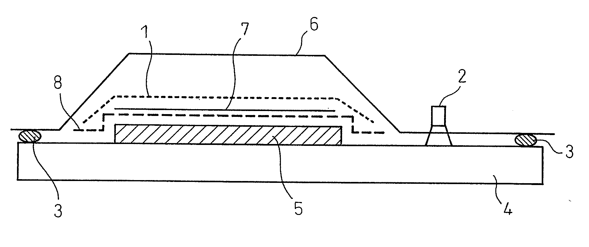
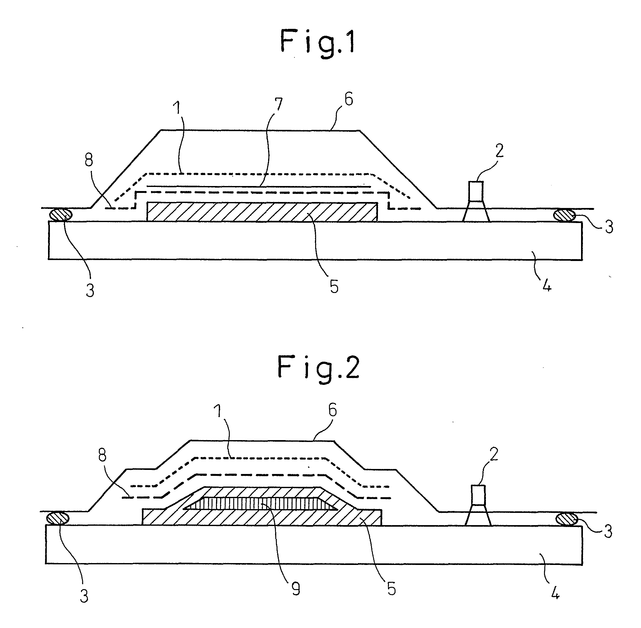
[0059]A TRK510 material by Mitsubishi Rayon Co., Ltd. was prepared as the fiber base material. With the basis weight of the resin film set for a resin content of 45 mass % in the prepreg, resin composition A was coated onto a release sheet with a film coater under 60° C. conditions, to obtain a resin film. The obtained resin film was attached onto both sides of the fiber base material, and passed through a fusing press (JR-600S, product of Asahi Corp., processing length: 1340 mm, pressure: cylinder pressure) under conditions with a temperature of 40° C., a pressure of 0.05 MPa and a feed rate of 1.6 m / min, to obtain prepreg 1. The resin content of the prepreg was 45 mass %. Upon cutting the obtained prepreg and visually observing the cross-section, interior sections without impregnation of the resin were seen. The obtained prepreg was laminated along the warp yarn direction, and the laminated body was bagged with the construction shown in FIG. 1. Also, a vacuum pump was connected to...

example 2

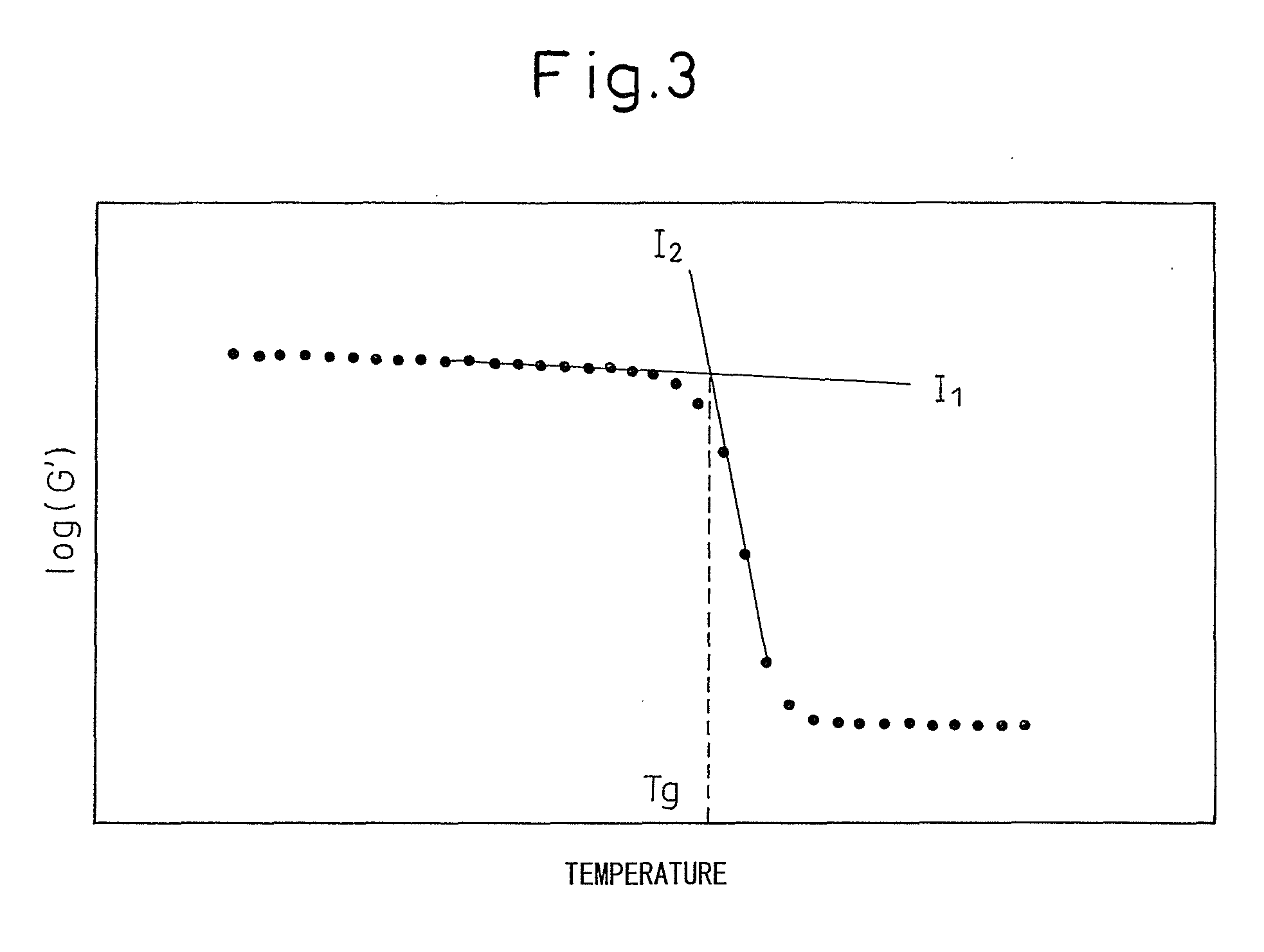
[0074]A sample was cut out from the cured resin sheet of resin composition A obtained in the same manner as Example 1, and the Tg was measured by DSC. The results are shown in Table 3.

example 3

[0075]Resin composition D was obtained by mixing jER828 and DY9577 at room temperature in the composition shown in Table 3. The obtained resin composition was placed in an aluminum dish and subjected to heat curing in an oven at 150° C. for 2 hours to obtain a cured resin. A sample was cut out from the obtained cured resin, and the Tg was measured by DSC. The results are shown in Table 3.


PUM

PropertyMeasurementUnit
Temperatureaaaaaaaaaa

Abstract

A prepreg comprising an epoxy resin (A), a boron chloride-amine complex (B) and a fiber base material (C) is used. Preferably, the molar ratio of boron in the boron chloride-amine complex (B) is 4-7 mol % with respect to the number of moles of epoxy groups in the epoxy resin (A), and the epoxy resin (A) includes a bifunctional epoxy resin with an oxazolidone ring structure, a bisphenol-type epoxy resin and a phenol-novolac-type epoxy resin.

Description

TECHNICAL FIELD[0001]The present invention relates to a prepreg, to a fiber-reinforced composite material obtained by curing it, and a method for producing it.BACKGROUND ART[0002]Fiber-reinforced composite materials, due to their light weight, high strength and high rigidity, are used for a wide range of purposes from sports and leisure to industrial purposes such as automobiles and aircrafts. In recent years, in particular, carbon fiber-reinforced composite materials with lighter weight, higher strength and higher rigidity have come to be used more often for industrial purposes.[0003]Among the industrial uses, carbon fiber-reinforced composite materials used in structural members of train cars and aircraft frames commonly employ prepregs as intermediate materials, and are produced by autoclave molding. This is designed to reduce voids in molded articles by molding under high pressure using an autoclave, and to exhibit the expected properties of the molded article.[0004]However, not...

Claims


Application Information

Patent Timeline
IPC IPC(8): B32B27/38B32B27/00B27N3/10
CPCB29C43/12C08J2363/00B29C43/3642B29C70/088B29C70/342B29C70/865B29C2043/3644B29K2063/00B29K2105/0854B29L2031/608B32B27/06B32B27/38C08G59/26C08G59/3218C08J5/24B29C43/3607C08J2363/04Y10T428/31511C08J5/249C08J5/243B29C65/02B32B37/06B32B37/10B29C66/712B29C66/7311B29C35/02B32B2363/00B29K2105/12B32B2307/306B32B2250/40
Inventor KANEKO, MANABUISHIMOTO, TOMOKOUSAMI, KAORI
Owner MITSUBISHI RAYON CO LTD
Why Eureka
Try Eureka