Spinal fixation system and screwdriver tool for use with the same

a fixation system and screwdriver technology, applied in the field of spine fixation system and screwdriver tool for use with the same, can solve the problems of poor, safe and secure placement of pedicle screws, affecting the accuracy of computer calculations, and affecting the patient, so as to improve the flow of bone cement through the screw, and prevent muscle or other tissu

Inactive Publication Date: 2012-08-09
LANGE ROBERT +1
View PDF9 Cites 116 Cited by
  • Summary
  • Abstract
  • Description
  • Claims
  • Application Information

AI Technical Summary

Benefits of technology

[0027]According to certain embodiments of the present invention, the grip has a rear end abutting a knob on the elongated guide element. The grip is longitudinally movable so it is capable of being shifted distally toward the engagement structure. During use, the grip can therefore be shifted distally until a distal end portion of the grip is disposed about and substantially covers the screw engagement unit. This helps shield the structures of the screwdriver tool at its distal end to thereby aid in the prevention of muscles or other tissue from becoming entangled and injured by the special screwdriver as the screw is threaded into bone. However, the grip can be manually shifted back from the shielded position in a proximal direction by the surgeon for inspection.
[0028]Another objective of certain embodiments of this invention is to provide a screwdriver that can be assembled and disassembled without a requirement for special tools. Especially designed structures of such embodiments also protect against accidental disassembly.
[0029]According to an embodiment of the present invention, the polyaxial bone screw assembly can include a fenestrated screw adapted to receive a bone cement injector. This embodiment is especially desirable when treating osteoporotic vertebra. The flow of bone cement through the screw is improved because the bone cement injector has a tapered outer surface adapted to engage the tapered recess surface formed in the head of the fenestrated bone screw. This improves the management of pressure through the cement injector and fenestrated screw system which is required to properly dose the amount of cement within an osteoporotic vertebra.
[0030]When treating patients with Osteoporosis and Osteopenia, it is advantageous to increase bone density. Even with bone density enhancements, the dangers of screw “pull-out” are ever present. A still further objective of this invention is to provide improved means to increase bone density by introducing bone density material through a fenestrated screw that preserves the advantages of the interengaging conical surfaces while combining that bone density advantage with a stabilizing rod that will absorb a limited amount of stress so that stress can be isolated from the screw / bone interface.
[0031]As mentioned previously, the present invention utilizes a rod made from a fiber-reinforced plastic. Such a composite rod can be used in combination with a solid screw or a fenestrated screw. The composite rod is preferably as strong but not as rigid, as a titanium rod having identical dimensions. Extreme stiffness is a disadvantage for pedicle fixation systems especially when used for treating osteoporotic vertebrae. Composite rods can be designed to be sufficiently strong to perform the required stabilizing function but with a degree of flexibility to isolate stress from the bone-screw interface and at the same time permitting a limited degree of stress to reach the bones under treatment. Additionally, a composite rod will not interfere with x-ray or other non-invasive inspections during the curative stage as do metallic rods.

Problems solved by technology

While this procedure is now commonly performed, a proper, safe and secure pedicle screw placement remains difficult for the surgeon and potentially dangerous for the patient.
These can be easily damaged by a threading screw should the screw escape the pedicle boundaries during insertion.
Due to the different inner and outer densities of bone, the resistance of the bone being threaded with a pedicle screw can change and this can be the surgeon's indication of proper and safe or incorrect and unsafe screw placement.
But the accuracy of the computer calculation is only as accurate as the trueness of the screw to instrument interface.
Too much micro stresses and strains causes micro stress fractures that can also kill bone cells.
However, they do not provide the many benefits of polyaxial assemblies.
However, when a stiff rod is subjected to stress, it will resist “give”.
This can cause a phenomenon called stress shielding where physiologic loads are propagated not through the bone, but instead around the bone and through the implant, causing insufficient micro stress and strain with associated bone resorption.
Pull-out can result.
Spinal stabilization operations are difficult and demanding on the operating physician.
This is sometimes referred to as a “wobble effect” that can reduce the effectiveness of the operating physician.
Wobble effect makes it difficult for the surgeon to thread a true and safe path into the unseen pedicle and it reduces the tactile “feed back” through the instrument that informs the surgeon if the screw is located in the softer inner or harder outer pedicle bone.
Instruments during the normal course of surgery can be accidently dropped upon a very hard operating or sterilization room floor and this can impact and bend the tip of the instrument that engages the screw.
If the surgeon rotates the handle to rotate the pedicle screw with one hand and grips the elongated guide element with the other hand, this can result in unscrewing the guide cylinder from the tulip and creating screw wobble making proper screw threading more and more difficult.
Even with bone density enhancements, the dangers of screw “pull-out” are ever present.
Extreme stiffness is a disadvantage for pedicle fixation systems especially when used for treating osteoporotic vertebrae.

Method used


Image

  • Spinal fixation system and screwdriver tool for use with the same
  • Spinal fixation system and screwdriver tool for use with the same
  • Spinal fixation system and screwdriver tool for use with the same

Examples


Embodiment Construction

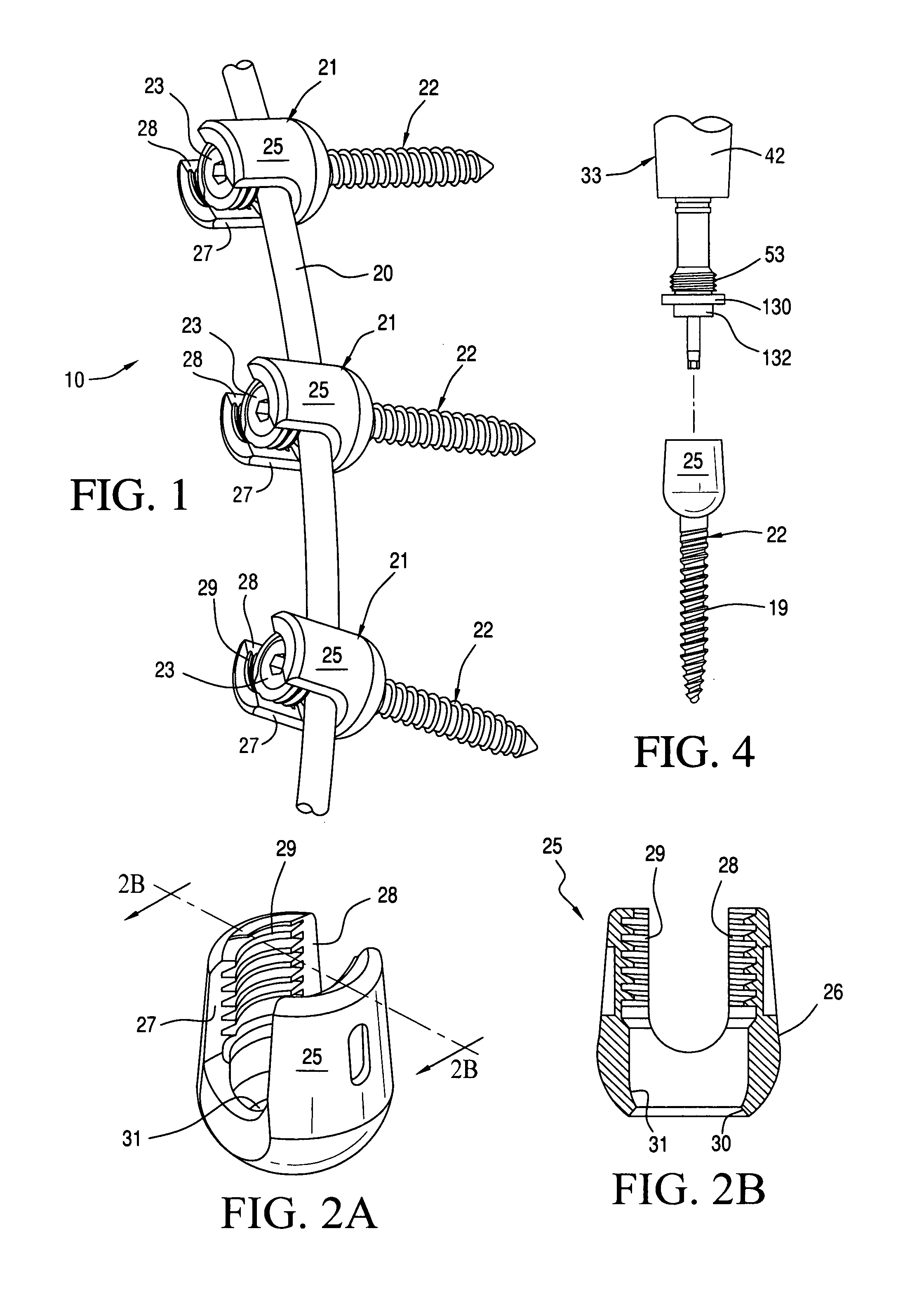
[0056]An exemplary spinal fixation system 10 is shown in accompanying FIG. 1. As depicted, the system 10 includes a composite rod 20 that is as strong as metallic spinal rods of like cross-sectional dimensions and length but, depending on the length, characteristics and amount of fiber embedded in the plastic, can be engineered to permit limited degrees of flexibility for reasons hereinafter described in more detail. See in this regard, U.S. Patent Application Publication Nos. 2008.0262548 and 2010 / 0042163 (the entire contents of each being expressly incorporated hereinto by reference).

[0057]As is well known in the art, the rod 20 will have a contour generally the same as that portion of the spine to be treated and will ultimately be located in a position generally parallel to that portion of the spinal column under treatment.

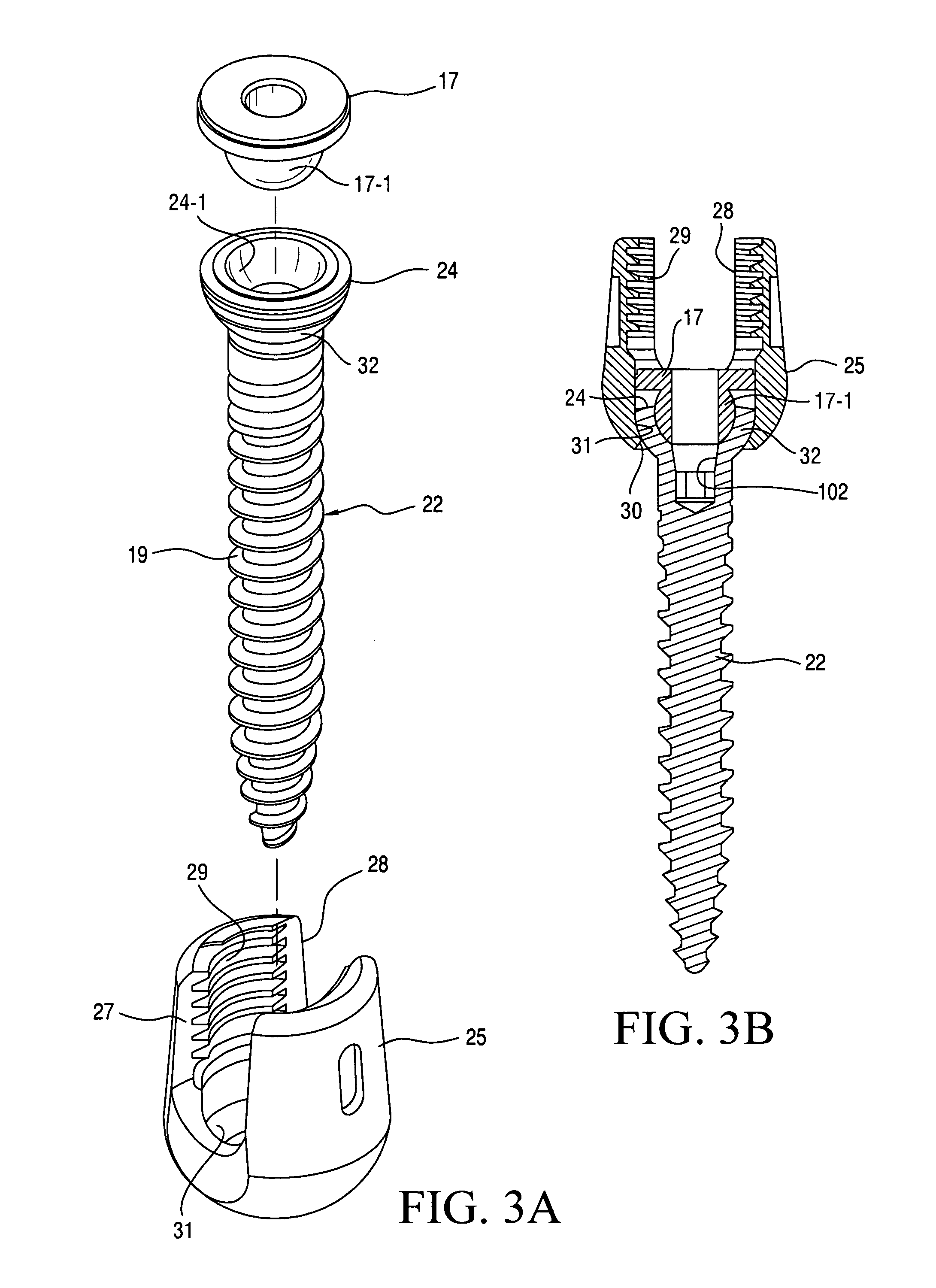
[0058]A series of pedicle screw / tulip assemblies 21 are secured to the rod 20. The screws 22 thereof are polyaxial—that is, their heads 24 are mounted for univ...


PUM


Abstract

A spinal fixation system that utilizes a composite rod to which polyaxial pedicle screw/tulip assemblies are secured, a screwdriver that permits independent threading of a guide member to the tulip and independent threading of the pedicle screw, together with interengaging conical surfaces that true the screwdriver with the pedicle screw. In preferred embodiments, the screwdriver includes an elongated drive shaft having a handle end for imparting rotation and a pedicle screw engaging end, a cylindrical guide member rotatably mounted about said drive shaft, a knob at one end of said guide member for rotating same and a threaded tulip engaging end at the other end thereof. A grip is preferably sleeved around the cylindrical drive member and is longitudinally movable between proximal and distal positions wherein its distal end uncovers and covers, respectively, the screw engaging unit.

Description

CROSS-REFERENCE TO RELATED APPLICATION[0001]This application is related to and claims priority benefits under 35 USC §119(e) from U.S. Provisional Application Ser. No. 61 / 272,526 filed on Oct. 5, 2009, the entire content of which is expressly incorporated hereinto by reference.FIELD[0002]The embodiments disclosed in this application relate generally to tools especially adapted for use with a spinal fixation system that includes a composite rod and a screw / tulip assembly.BACKGROUND AND SUMMARY[0003]A surgeon undertaking a spinal fixation installation has four concurrent goals:[0004](1) Correcting the spinal difficulty, such as degeneration or deformity. To achieve this, the spinal fixation system must apply a corrective force upon the spine.[0005](2) Stabilizing the spinal segments to be treated so that the correction and alignment is maintained. To achieve this, the spinal fixation system must allow some deflection and then return resiliently due to inherent memory to the form desir...

Claims


Application Information

Patent Timeline
Patent Type & Authority Applications(United States)
IPC IPC(8): A61B17/86A61B17/56
CPCA61B17/7082
Inventor LANGE, ROBERTBIHL, ANDREAS
Owner LANGE ROBERT
Why Eureka
Try Eureka