
Wind turbine control methods for improving the production of energy

a technology of wind turbines and control methods, which is applied in the direction of electric generator control, machines/engines, mechanical equipment, etc., can solve the problems of limitation of wind energy captured with respect to the wind energy available, the rotational speed of wind turbines implies a limitation of wind turbine loads, etc., and achieves the effect of optimizing energy production

Inactive Publication Date: 2012-08-16
GAMESA INNOVATION & TECH SA
View PDF2 Cites 13 Cited by
  • Summary
  • Abstract
  • Description
  • Claims
  • Application Information

AI Technical Summary

Benefits of technology

[0007]It is an object of the present invention to provide wind turbines controlled by control methods that allow the optimization of the energy production.
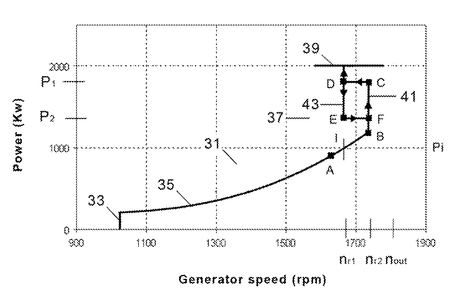
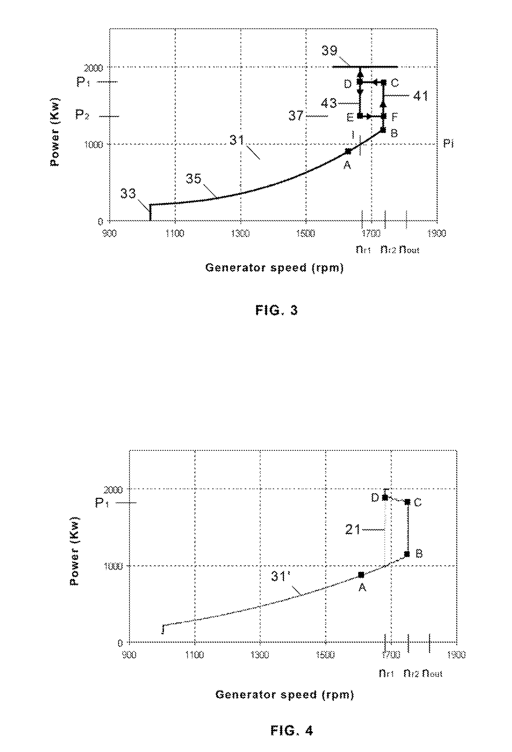
[0011]In another preferred embodiment said first vertical segment and said second vertical segment have, respectively, upper and lower points C, E at two power predetermined values P1, P2 defining the paths C-D; E-F to be followed between them. Hereby it is achieved a control method that optimize the energy production minimizing the drawbacks associated to the use of said first and second vertical segments.
[0012]In another preferred embodiment said power value P1 is comprised in a range of 85%-95% the power nominal value. Hereby it is achieved a control method that optimize the energy production minimizing the drawbacks associated to high torques and high angular speeds.
[0013]In another preferred embodiment said power value P2 is comprised in a range of 110% Pi-90% P1, being Pi the value of the power at the intersection point I between the second sub-nominal zone and a vertical line at the generator nominal speed nr1. Hereby it is achieved a control method that optimize the energy production minimizing the drawbacks associated to fatigue loadings.
[0014]In another aspect the above-mentioned objects are met by providing a variable speed wind turbine controlled by the above-mentioned method. In a preferred embodiment, the wind turbine generator is a doubly fed induction generator. Hereby it is achieved a way for improving the energy production of many already installed wind turbines.

Problems solved by technology

As it is well known the limitation of the rotational speed of wind turbines implies a limitation of the wind turbine loads and also a limitation of the wind energy captured with respect to the wind energy available.

Method used


Image

  • Wind turbine control methods for improving the production of energy
  • Wind turbine control methods for improving the production of energy
  • Wind turbine control methods for improving the production of energy

Examples


Embodiment Construction

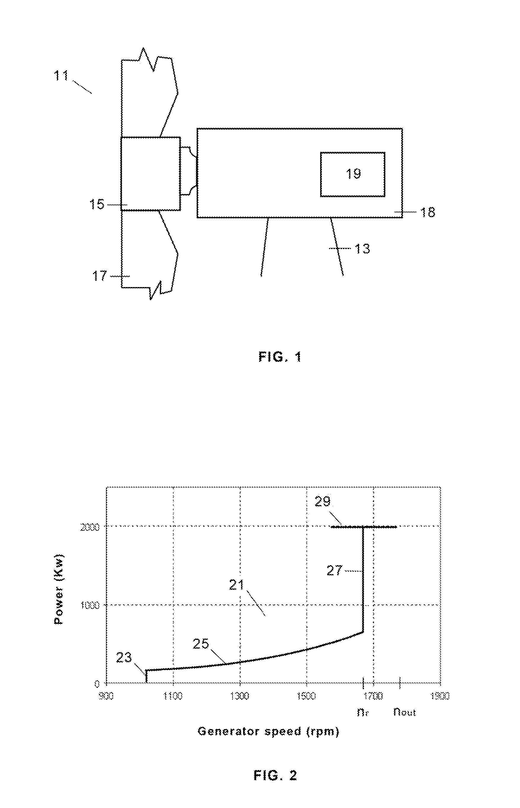
[0023]A typical wind turbine 11 comprises a tower 13 supporting a nacelle 18 housing a generator 19 for converting the rotational energy of the wind turbine rotor into electrical energy. The wind turbine rotor comprises a rotor hub 15 and, typically, three blades 17. The rotor hub 15 is connected either directly or through a gearbox to the generator 19 of the wind turbine for transferring the torque generated by the rotor 15 to the generator 19 and increase the shaft speed in order to achieve a suitable rotational speed of the generator rotor.

[0024]The power output from a modern wind turbine is typically controlled by means of a control system for regulating the pitch angle of the rotor blades and the generator torque. The rotor rotational speed and power output of the wind turbine can hereby be initially controlled e.g. before a transfer to a utility grid through a converter.

[0025]The basic aim of the methods of operation of variable speed wind turbines is to achieve an operation a...


PUM


Abstract

Method of operation of a variable speed wind turbine (11) having control means for its regulation tracking a power vs. generator speed curve (31) comprising a nominal zone (39) where the power is kept constant at a nominal value, a first sub-nominal zone (33) where the generator speed is kept constant at its coupling value, a second sub-nominal zone (35) where both generator speed and power are allowed to increase / decrease in line with wind speed and a third sub-nominal zone (37) between the second sub-nominal zone (35) and the nominal zone (39) that comprises a first vertical segment (41) at a generator speed nr2 higher than the generator nominal speed nr1 and a second vertical segment (43) at the generator nominal speed nr1 connecting with the nominal zone (39), each of both segments (41, 43) to be followed in function of the wind speed changes for optimizing the energy production.

Description

FIELD OF THE INVENTION[0001]The invention relates to variable speed wind turbine control methods and, in particular, to variable speed wind turbine control methods for improving the production of energy.BACKGROUND[0002]Wind turbines are devices that convert mechanical energy to electrical energy. A typical wind turbine includes a nacelle mounted on a tower housing a drive train for transmitting the rotation of a rotor to an electric generator and other components such as a yaw drive which rotates the wind turbine, several controllers and a brake. The rotor supports a number of blades extending radially therefrom for capturing the kinetic energy of the wind and causing the driving train rotational motion. The rotor blades have an aerodynamic shape such that when a wind blows across the surface of the blade, a lift force is generated causing the rotation of a shaft which is connected—directly or through a gearing arrangement—to the electrical generator located inside the nacelle. The ...

Claims


Application Information

Patent Timeline
Patent Type & Authority Applications(United States)
IPC IPC(8): H02P9/04
CPCF03D7/0276F03D7/028F03D7/043Y02E10/723F05B2270/103F05B2270/20F05B2270/101Y02E10/72F03D7/022
Inventor GARCIA ANDUJAR, JUAN CARLOSLOPEZ RUBIO, JOSE MARIA
Owner GAMESA INNOVATION & TECH SA
Learn More