Dynamic multifocal contact lens

a multi-focal, contact lens technology, applied in the field of adjustable power contact lens, can solve the problems of reducing the refractive power of the eye, degrading the view of an image, and many people encounter difficulty in focusing, and achieve the effect of low manufacturing cos

Inactive Publication Date: 2012-08-16
IWAI BENJAMIN T
View PDF3 Cites 41 Cited by
  • Summary
  • Abstract
  • Description
  • Claims
  • Application Information

AI Technical Summary

Benefits of technology

[0029]Another object is to provide such an adjustable power contact lens that allows presbyopic persons to use their near vision and view nearby objects without changing contacts or wearing eyeglasses.
[0030]Another object is to provide such an adjustable power

Problems solved by technology

Reaching the age of forty years, many people then encounter difficulty in focusing because of this eye lens thickening, or presbyopia, where the eye decreases its refractive power.
The person then sees multiple exposures of an image resulting in a degraded view of an image, that is stacked, blurr

Method used


Image

  • Dynamic multifocal contact lens
  • Dynamic multifocal contact lens
  • Dynamic multifocal contact lens

Examples


embodiment 2

[0105]FIG. 5 shows a front view of the second embodiment of the invention 1 with its first layer 50 in the foreground. This first layer is of soft contact lens material where soft material adapts to the corneal surface immediately. The first layer is of transparent construction and round shape with a diameter proportional to the iris of a person. The first layer has a round first edge 51 defining its perimeter. Inwardly from the first edge, the lens has the loop antenna 4 that generally follows the first edge though at slightly less diameter and has its two terminals 4a. The terminals connect the antenna 4 to the first electromagnet 5 as described above. The outer edge defines the maximum width of the first electromagnet.

[0106]Generally, this embodiment comprises a contact lens with two annular electromagnets embedded in the layers of the lens as later shown. The electromagnets have a preferred circular form that provides the desired shape when engaged for vision correction of a use...

embodiment 3

[0117]FIG. 9 shows a front view of the third embodiment of the invention 1 with its first layer 60 in the foreground. This first layer is of soft contact lens material that adapts to the corneal surface immediately. The first layer is of transparent construction and round shape with a diameter proportional to the iris of a person. The first layer has a round first edge 61 defining its perimeter. Inwardly from the first edge, the lens has the loop antenna 4 that generally follows the first edge though at slightly less diameter and has its two terminals 4a for connecting to the first electromagnet 5 as described above. The outer edge 6 defines the maximum width of the first electromagnet.

[0118]Generally, this embodiment comprises a contact lens of two layers in a piggyback arrangement with two annular electromagnets, one embedded in each of the two layers of the lens but without a core as later shown. The electromagnets have a preferred circular form that provides the desired shape wh...

embodiment 4

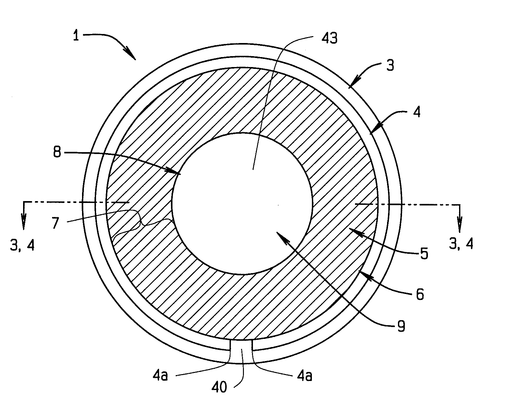
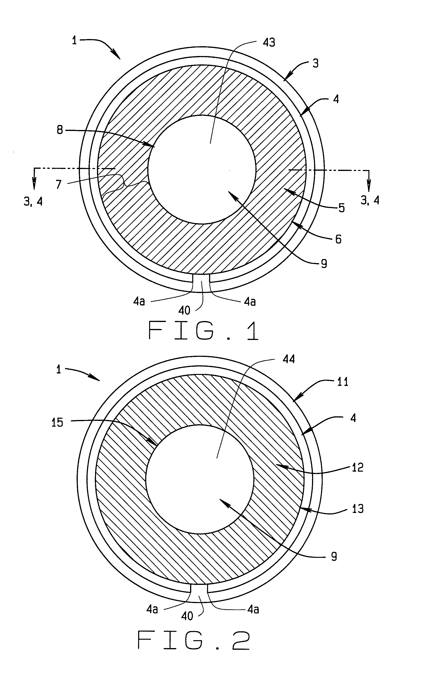
[0126]And the fourth embodiment provides at least two focal lengths, or powers in a single lens. FIG. 13 shows a front view of the invention 1 with its first layer 2 in the foreground. The first layer is of soft lens material that readily adapts to a patient's cornea and has a generally transparent construction and round shape with a diameter proportional to the iris of a person. The first layer has a round first edge 3 defining its perimeter. Inwardly from the first edge, the lens of the invention 1 has a loop antenna 4 that generally follows the first edge though at slightly less diameter. The antenna has two terminals 4a here shown spaced apart though proximate each other. The terminals connect the antenna 4 to the first electromagnet 5 that has a round annular shape with an outer edge 6 slightly less in diameter than the loop antenna. The outer edge defines the maximum width of the first electromagnet.

[0127]This embodiment comprises a contact lens with two annular electromagnets...


PUM


Abstract

An dynamic multiple focus contact lens has at least one transparent layer with a first annular electromagnet and a second annular electromagnet, a transparent pupil allowing passage of light through the at least one layer, at least one loop antenna in communication with the electromagnets, and a transmitter for activating the electromagnets. The at least one layer has a first shape similar to a circular segment that follows the surface of the cornea. The first shape has a first focal length, or power. Upon initiation by a user, a transmitter sends a signal to the loop antenna which energizes the electromagnets to mutually attract causing the at least one layer to deflect and the central portion of the first layer to deform outwardly forming the layer into a second shape. The second shape has a second power, stronger than the first shape.

Description

CROSS-REFERENCE TO RELATED APPLICATION[0001]This non-provisional application claims priority to the pending provisional application 61 / 441,517 filed on Feb. 10, 2011 which is owned by the same inventor.BACKGROUND OF THE INVENTION[0002]The adjustable power contact lens generally relates to optometry and more specifically to adjustable focal length lenses for the eye. The invention relates to a contact lens placed upon an eye that has an initial focal length and then a second focal length upon energizing embedded electromagnets.[0003]Over the last three centuries, people have corrected vision problems, such as blurry vision, using solid transparent lenses. The lenses have been placed in frames and worn external of the affected eyes, typically known as eyeglasses or glasses. The lenses may have a single focal length, or power, or multiple powers such as in bi-focals and tri-focals. Multiple power lenses can be made of stacked pieces of lens, with the known bifocal line showing. Recentl...

Claims


Application Information

Patent Timeline
IPC IPC(8): G02C7/04
CPCG02C7/085G02C7/041
Inventor IWAI, BENJAMIN T.
Owner IWAI BENJAMIN T
Why Eureka
Try Eureka