Unlock instant, AI-driven research and patent intelligence for your innovation.
Estimation of Sample Clock Frequency Offset Using Error Vector Magnitude
Active Publication Date: 2012-08-16
NATIONAL INSTRUMENTS
View PDF0 Cites 56 Cited by
Summary
Abstract
Description
Claims
Application Information
AI Technical Summary
This helps you quickly interpret patents by identifying the three key elements:
Problems solved by technology
Method used
Benefits of technology
Benefits of technology
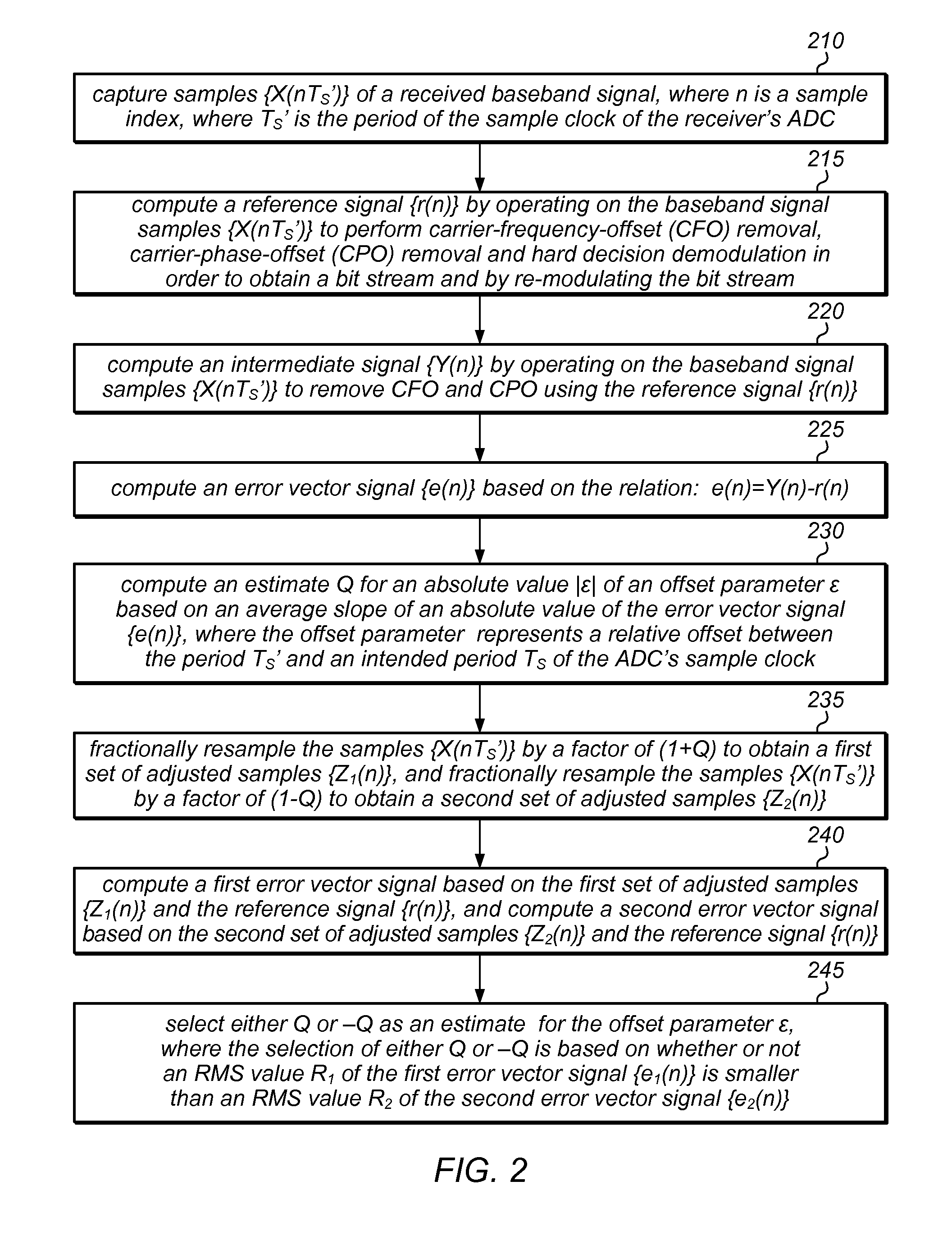
[0025]The method also involves the processor selecting either Q or −Q as an estimate for the offset parameter ε, where the selection of either Q or −Q is based on whether or not an RMS value R1 of the first error vector signal is smaller than an RMS value R2 of the second error vector signal. T
Problems solved by technology
This offset between the intended clock rate 1 / TS and the actual clock rate 1 / TS′ makes it difficult to accurately demodulate the received baseband signal.
Method used
Image
Click on the blue label to locate the original text in one second.
Reading with bidirectional positioning of images and text.
Examples
case-i
[0100] Assuming that the intermediate signal Y(n) has no CFO or CPO, the error vector e(n) may be written as:
[0101]This expression (10) may be simplified, by making the following assumptions:
[0102](A1) A(nTS′)=A(nTS) for all n. This assumption is made because the difference between A(nTS) and A(nTS′) is a significantly smaller contributor to error vector e(n) than is the difference between α(nTS) and a(nTS′).
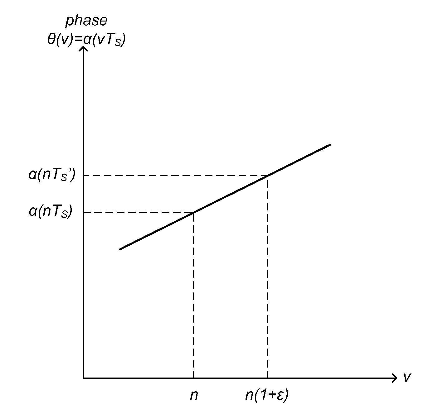
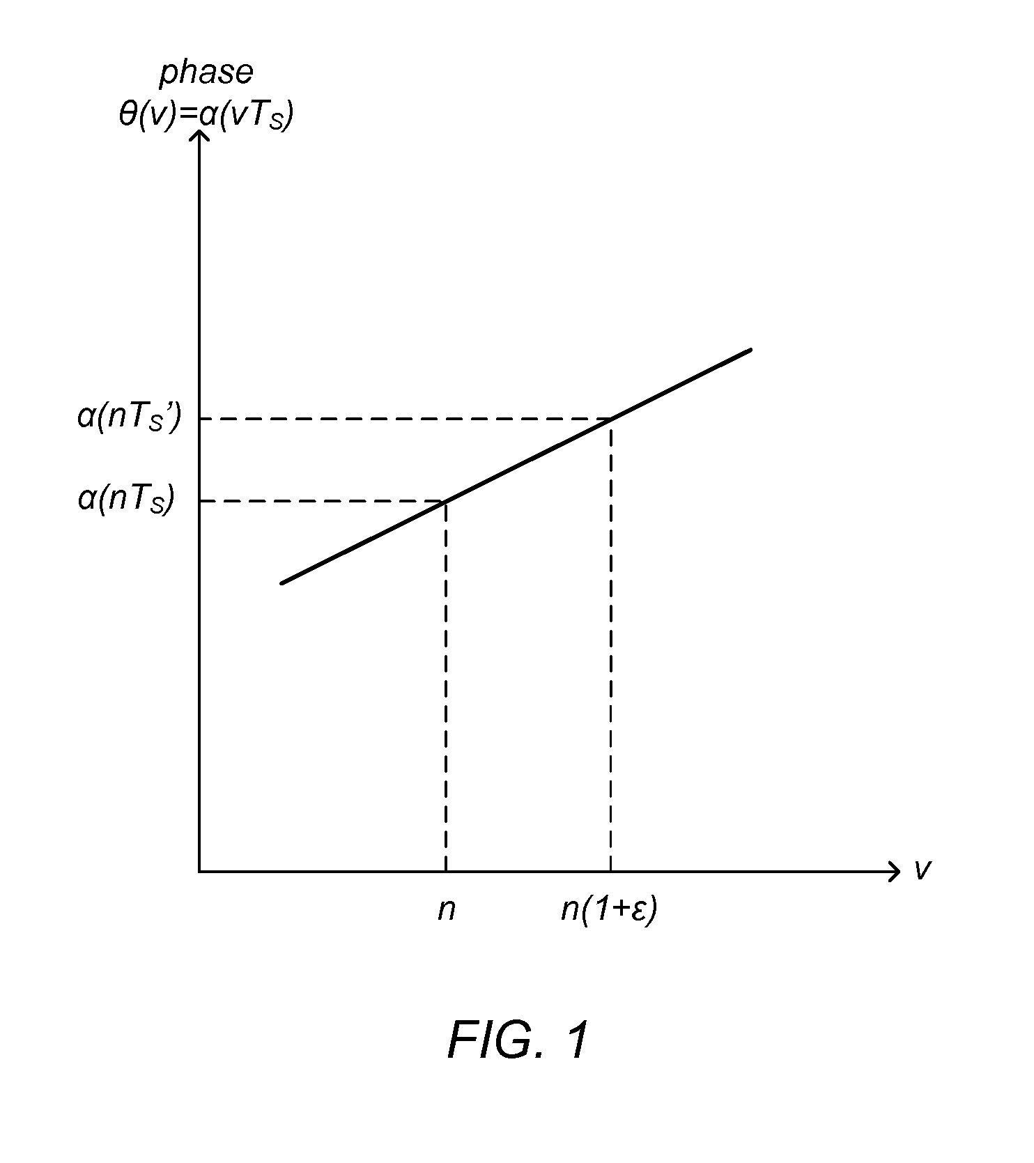
[0103](A2) The phase α(t) is assumed to be linear between any intended sampling time nTS and the corresponding actual sampling time nTS′=(1+ε)nTS. This linearity is illustrated in FIG. 1.
[0104](A3) The accumulated error in clock phase is low enough not to cause a significant number of hard decision errors over the range of the received sample set.
[0105]Employing these assumptions, expression (10) may be rewritten as:
where β(n)=α(nTS′)−α(nTS). The absolute value of the error vecto...
case-ii
[0115] Assuming that the intermediate signal Y(n) has both residual CFO and residual CPO, the error vector e(n) may be written as:
e(n)=Y(n)−r(n) (20A)
e(n)=A(nTS′)exp{j(α(nTS′)+Δθ+Δω0′nTS′)}
−A(nTS)exp{jα(nTS)}. (20B)
Observe that this expression involves three unknowns: TS′, Δω0′ and Δθ (or equivalently, ε, Δω0′ and Δθ).
[0116]It is a fundamental fact that by performing the differential of any signal {v(n)}, the CFO in the signal {v(n)} will manifest as a constant phase offset error in the differential signal, and the phase offset present in the signal {v(n)} will be removed from the differential signal. The differential signal ∇v(n) is defined as:
∇v(n)=v(n)v(n−1)*. (21)
[0117]The error vector e′(n) corresponding to the differential of the intermediate signal Y(n) and the differential of the reference signal r(n) is given by:
e′(n)=∇Y(n)−∇r(n). (22)
[0118]Applying the definition of differential to the intermediate signal Y(n), one obtains:
∇Y(n)=A(nTS′)A((n−1)TS′)exp{j(α(nTS′)−α((n−1)T...
embodiment 1100
[0202]FIG. 11 illustrates one possible embodiment 1100 of computer system 1000. Although the embodiments above have been described in considerable detail, numerous variations and modifications will become apparent to those skilled in the art once the above disclosure is fully appreciated. It is intended that the following claims be interpreted to embrace all such variations and modifications.
PUM
Abstract
A low complexitysystem and method for operating a receiver in order to estimate an offset between the actual sample clock rate 1 / TS′ of a receiver and an intended sample clock rate 1 / TS. The receiver captures samples of a received basebandsignal at the rate 1 / TS′, operates on the captured samples to generate an estimate for the clock rate offset, and fractionally resamples the captured samples using the clock rate offset. The resampled data represents an estimate of baseband symbols transmitted by the transmitter. The action of operating on the captured samples involves computing an error vector signal and then estimating the clock rate offset using the error vector signal. The error vector signal may be computed in different ways depending on whether or not carrier frequency offset and carrier phase offset are assumed to be present in the received baseband signal.
Description
BACKGROUND OF THE INVENTION[0001]1. Field of the Invention[0002]The present invention relates to the field of digital signalprocessing, and more specifically, to systems and methods for estimating the offset between the actual sample-clock-frequency used by a receiver's analog-to-digital converter and an intended sample-clock-frequency.[0003]2. Description of the Related Art[0004]At a transmitter, a stream of information bits is mapped into a stream of complex symbols {Un} in a constellation (i.e., a set of points in the complex plane), e.g., a QAMconstellation. The stream of symbols {Un} may be supplied to a subsystem that converts the symbol stream into an analog baseband signal u(t). The analog baseband signal u(t) may be used to modulate a carrier signal. The modulated carrier is transmitted through a channel, e.g., a wired channel such as a cable, a wireless channel such as the atmosphere or free space, a fiber optic channel, etc. A receiver captures a channel-distorted versi...
Claims
Application Information
Patent Timeline
Application Date:The date an application was filed.
Publication Date:The date a patent or application was officially published.
First Publication Date:The earliest publication date of a patent with the same application number.
Issue Date:Publication date of the patent grant document.
PCT Entry Date:The Entry date of PCT National Phase.
Estimated Expiry Date:The statutory expiry date of a patent right according to the Patent Law, and it is the longest term of protection that the patent right can achieve without the termination of the patent right due to other reasons(Term extension factor has been taken into account ).
Invalid Date:Actual expiry date is based on effective date or publication date of legal transaction data of invalid patent.
IPC IPC(8): H04L27/06
CPCH04L7/0087H04L7/033H03M1/1255
Inventor AHMED, I. ZAKIRBHARADWAJ, KRISHNAKRISHNAN, RAMESHYAJNANARAYANA, VIJAYA
