Audio processing apparatus and method of controlling the audio processing apparatus

a technology of audio processing apparatus and audio signal, which is applied in the direction of stereophonic circuit arrangement, electrical transducers, instruments, etc., can solve the problems of large quantization error, large quantization error of above-described a/d converter, and noise in the audio signal acquired from the microphone, so as to suppress the increase of quantization error

Inactive Publication Date: 2012-08-16
CANON KK
View PDF3 Cites 60 Cited by
  • Summary
  • Abstract
  • Description
  • Claims
  • Application Information

AI Technical Summary

Benefits of technology

[0006]The present invention provides a high-quality audio by suppressing an increase in the quantization error by gain control after wind noise processing.

Problems solved by technology

In these audio processing apparatuses, an audio signal acquired from a microphone may contain noise due to the influence of wind.
However, in the conventional technique disclosed in Japanese Patent Laid-Open No. 2008-129107, the quantization error may become large upon gain control after wind noise processing.
For example, according to the method of Japanese Patent Laid-Open No. 2008-129107, when the gain controller increases the gain, the quantization error of the above-described A / D converter becomes large.

Method used


Image

  • Audio processing apparatus and method of controlling the audio processing apparatus
  • Audio processing apparatus and method of controlling the audio processing apparatus
  • Audio processing apparatus and method of controlling the audio processing apparatus

Examples


first embodiment

[0025]An audio recorder serving as an audio processing apparatus and an image capture device including the audio recorder according to the first embodiment of the present invention will be described below with reference to FIGS. 1 to 11A and 11B.

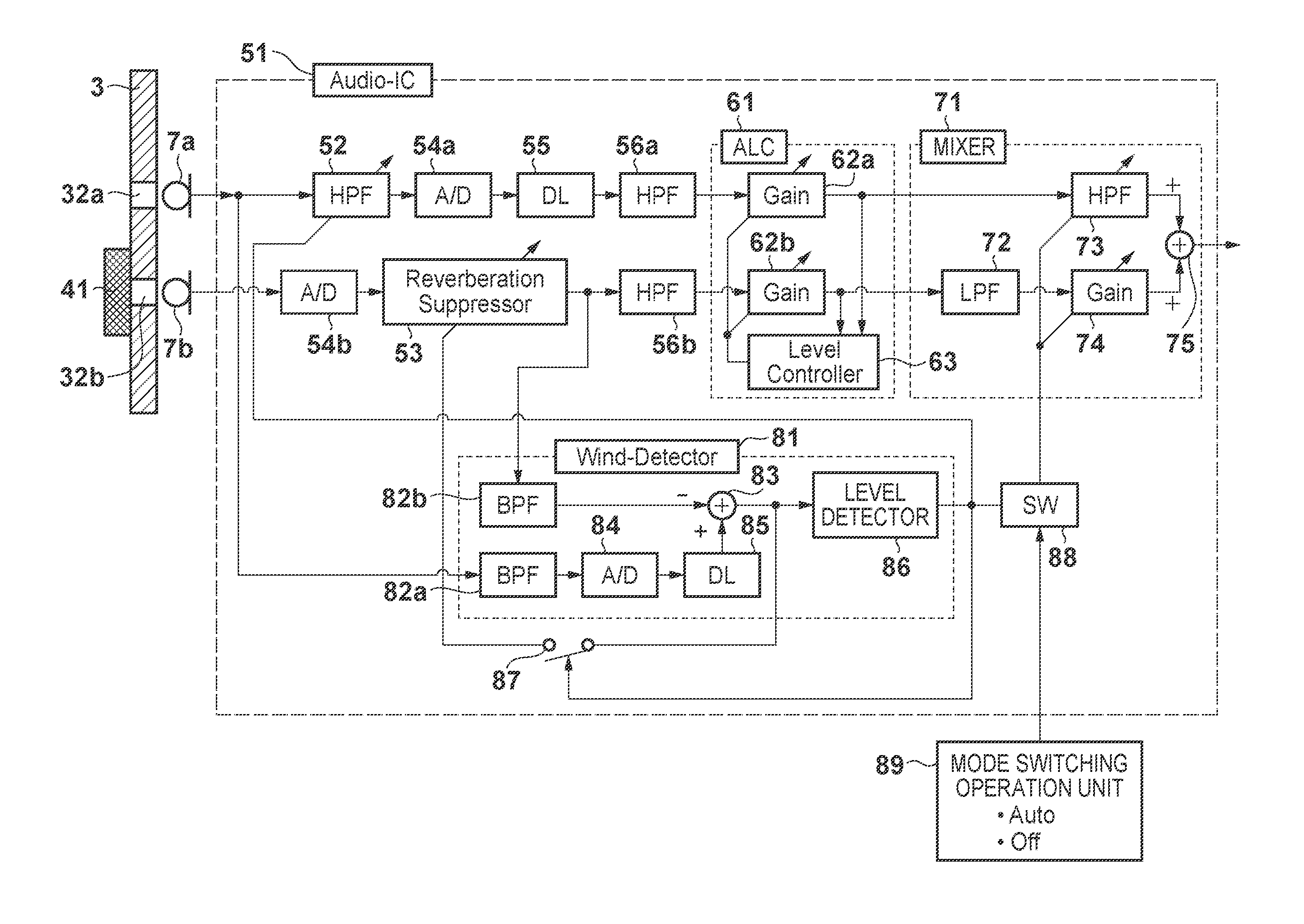
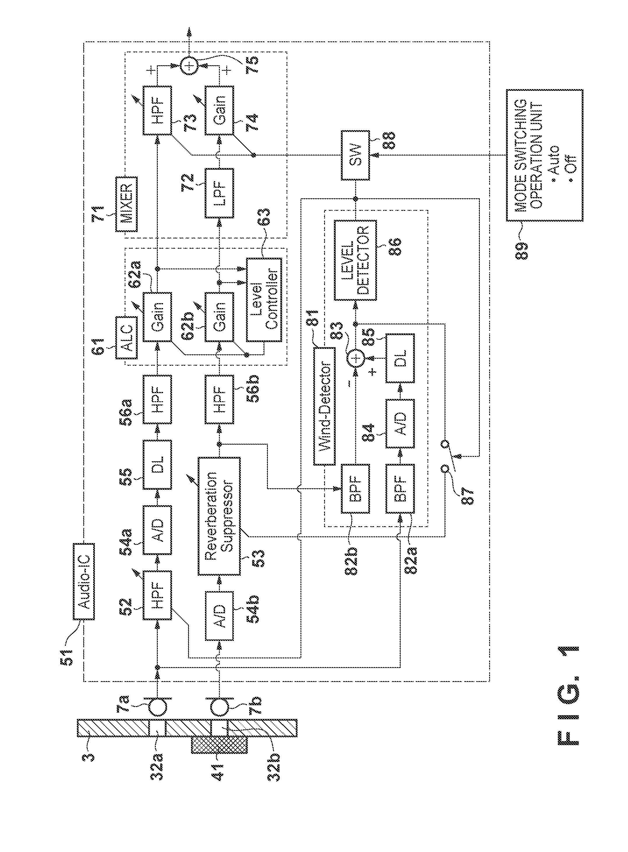
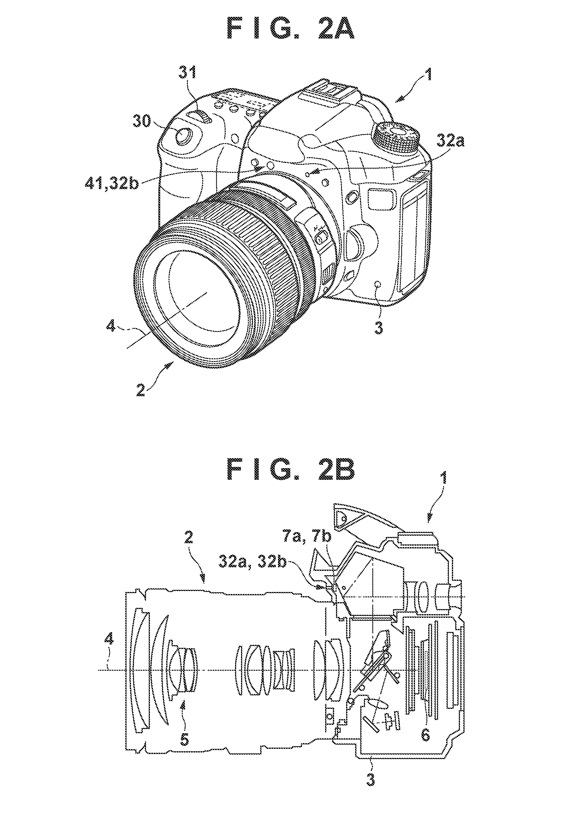
[0026]FIG. 1 is a block diagram showing the arrangement of the audio recorder according to this embodiment. FIGS. 2A and 2B are perspective and sectional views, respectively, showing the image capture device (camera) including the audio recorder shown in FIG. 1. Reference numeral 1 denotes an image capture device; 2, a lens attached to the image capture device 1; 3, a body of the image capture device 1; 4, an optical axis of the lens; 5, a photographing optical system; and 6, an image sensor. Reference numeral 30 denotes a release button; and 31, an operation button. A first microphone 7a and a second microphone 7b are provided in the image capture device 1. Opening portions 32a and 32b are provided in the body 3 for the microphones 7a and 7...

second embodiment

[0098]An audio recorder and an image capture device including the audio recorder according to the second embodiment of the present invention will be described below with reference to FIGS. 12 and 13. The same reference numerals as in the first embodiment denote parts that perform the same operations in the second embodiment.

[0099]FIG. 12 is a perspective view showing the image capture device. Although the apparatus in FIG. 12 is similar to that of FIG. 2A, an opening portion 32c for a microphone is added. A microphone 7c (not shown) is provided behind the opening portion 32c.

[0100]FIG. 13 is a block diagram for explaining the main part of an audio processing apparatus 51 corresponding to the apparatus shown in FIG. 12. In FIG. 13, the arrangement is extended to a stereo system based on the circuit including the ALC in the analog part according to the first embodiment shown in FIG. 11A. The illustrations of a reverberation suppressor 53 and a level detector 86 are simplified / changed...


PUM


Abstract

An audio processing apparatus includes first and second audio pickup units. The second audio pickup unit includes an audio resistor provided to cover a sound receiving portion to suppress external wind introduction while passing an external audio. A first filter attenuates a signal having a frequency lower than a first cutoff frequency of the output signal of a first A/D converter. A second filter attenuates a signal having a frequency higher than a second cutoff frequency of the output signal of a second A/D converter. A third filter is provided between the first audio pickup unit and the first A/D converter to attenuate a signal having a frequency lower than a third cutoff frequency for suppressing the wind noise.

Description

BACKGROUND OF THE INVENTION[0001]1. Field of the Invention[0002]The present invention relates to an audio processing apparatus and a method of controlling the audio processing apparatus.[0003]2. Description of the Related Art[0004]Video cameras, IC recorders, and the like are conventionally known as audio processing apparatuses. In these audio processing apparatuses, an audio signal acquired from a microphone may contain noise due to the influence of wind. As a countermeasure, some apparatuses provide a gain controller before an A / D converter to prevent an audio signal that has passed through the A / D converter from being saturated, and also remove low-frequency components to reduce wind noise in the audio signal that has passed through the A / D converter. For example, Japanese Patent Laid-Open No. 2008-129107 discloses a method of obtaining a high-quality audio by providing a gain controller before an A / D converter and also providing a gain controller after a low-frequency removing u...

Claims


Application Information

Patent Timeline
Patent Type & Authority Applications(United States)
IPC IPC(8): H04B3/20H04B15/00
CPCH04R1/245H04R2410/07H04R2430/01H04R5/027G10L21/034H04S2400/15H04R3/005G10L21/0208G10L2021/02165H04R5/04
Inventor KIMURA, MASAFUMIKAJIMURA, FUMIHIROWASHISU, KOICHI
Owner CANON KK
Why Eureka
Try Eureka