

Gas turbine engine component
- Summary
- Abstract
- Description
- Claims
- Application Information
AI Technical Summary
Benefits of technology
Problems solved by technology
Method used
Image

Examples
Embodiment Construction
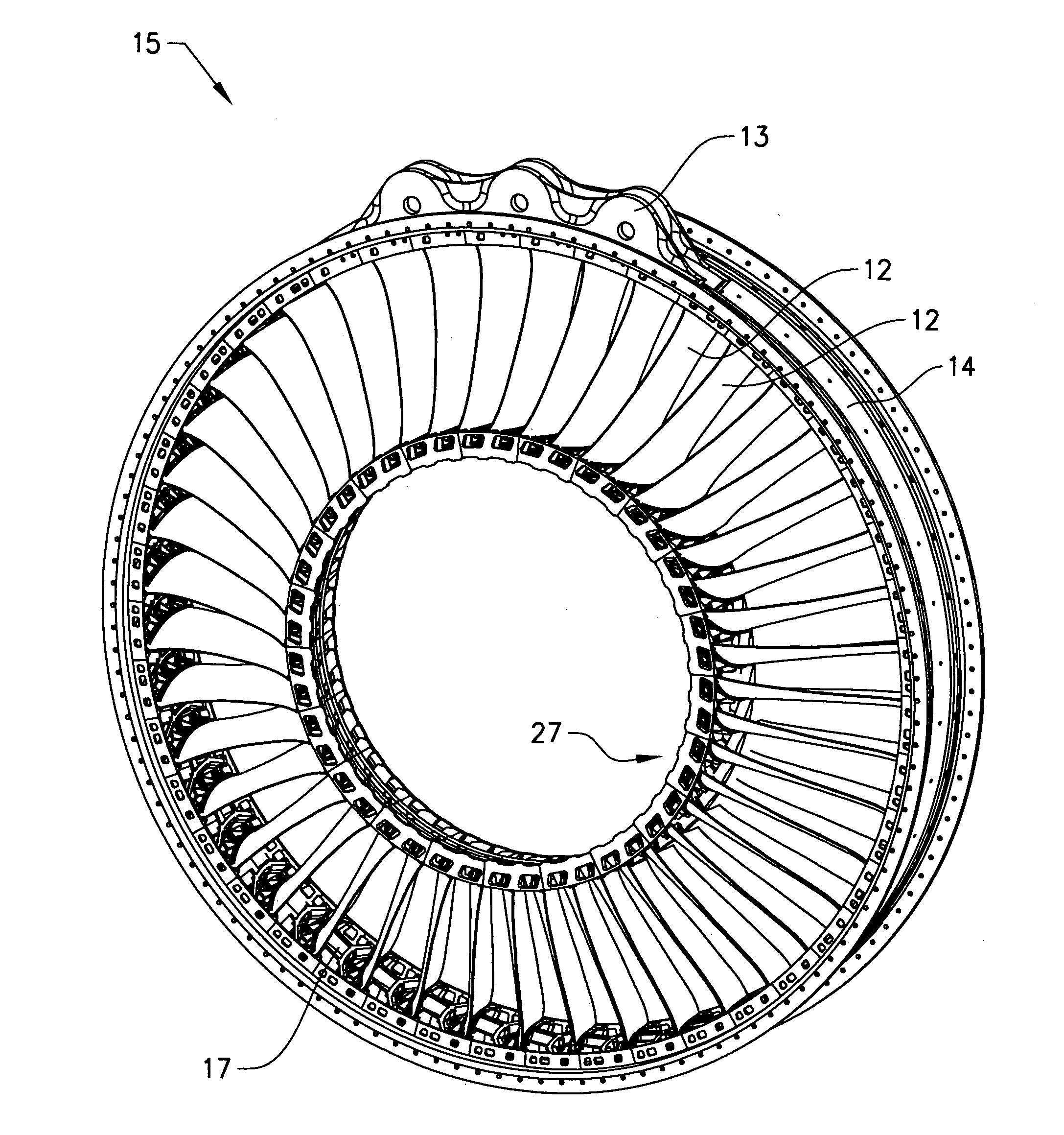
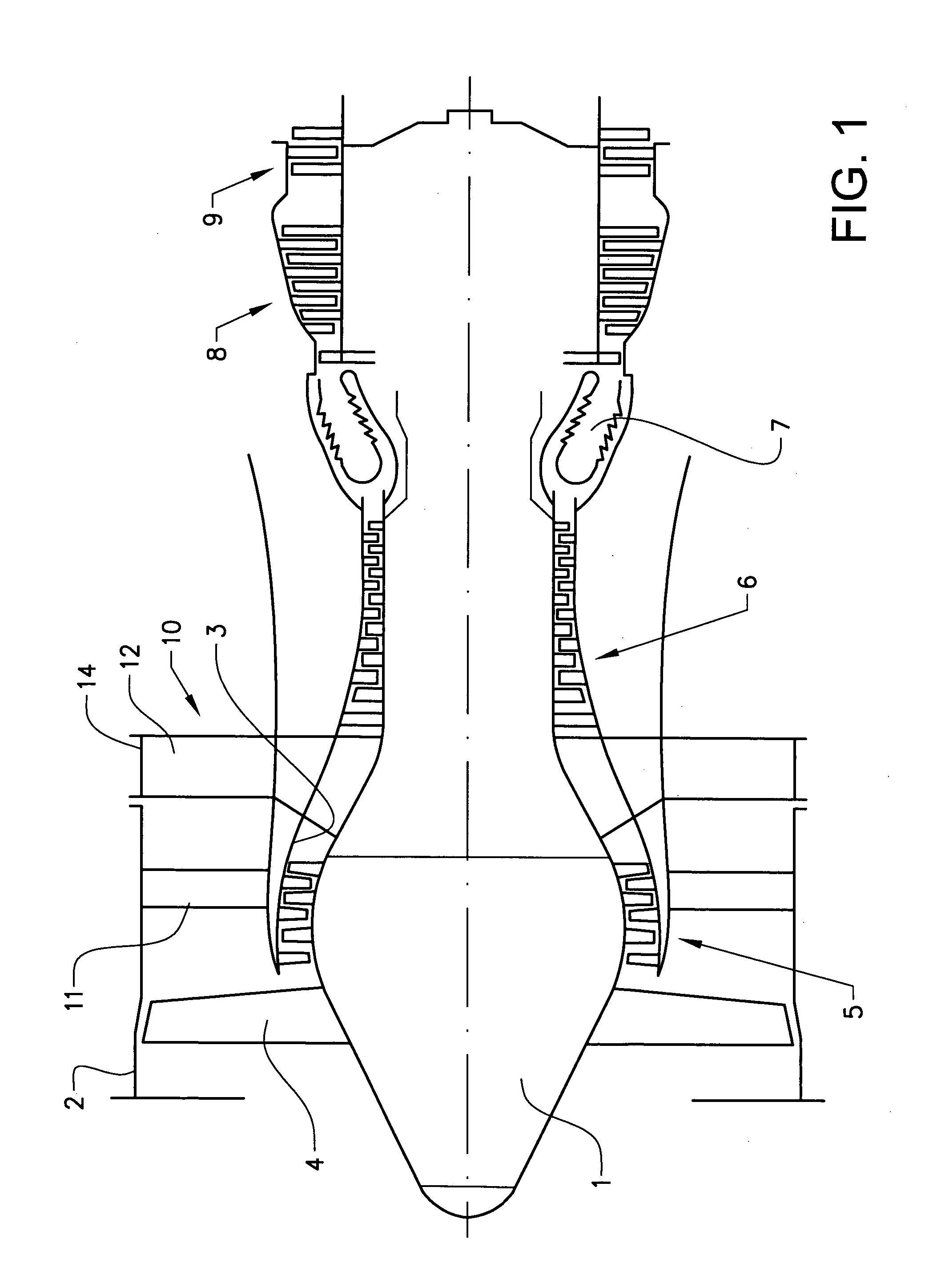
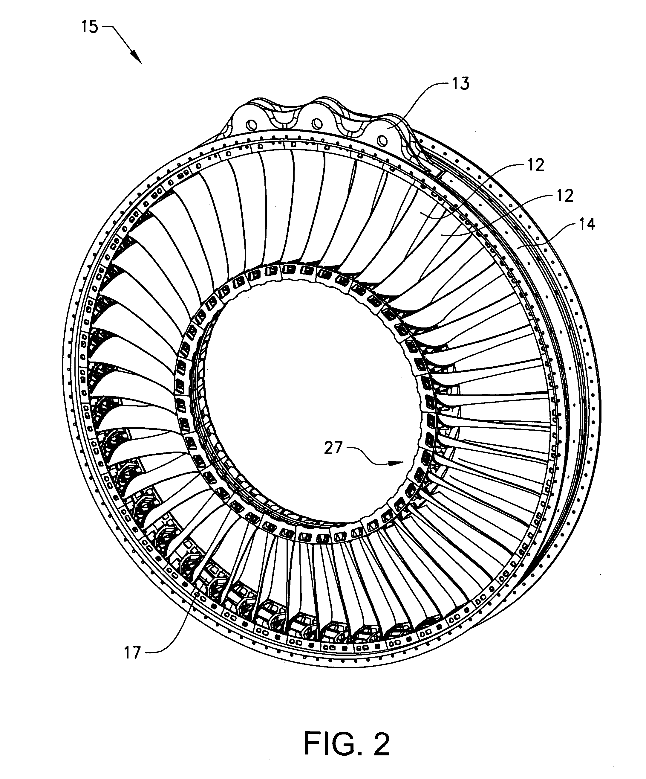
[0026]FIG. 1 shows a turbojet engine. The turbojet engine comprises a central body 1, an annular outer casing 2 (fan casing), an annular inner casing 3 (engine casing), a fan or blower 4, a low pressure compressor 5, a high pressure compressor 6, a combustion chamber 7, a high pressure turbine 8 and a low pressure turbine 9. It further comprises a set of arms 10 extending in a radial direction from the inner casing 3 to an outer ring element 14 forming part of the outer casing 2. The arms 10 comprise aerodynamic vanes 11 primarily provided to act as guide vanes for air passing through the annular channel between the inner casing 3 and the outer casing 2 in an axial direction, i.e. a longitudinal direction, of the engine. The arms 10 further comprise structural arms or load carrying vanes 12 primarily provided to guarantee a certain mechanical strength of the construction. Here, the aerodynamic vanes 11 and the load carrying vanes 12 are arranged in axially separated sets of arms. Ho...
PUM
 Abstract
Description
Claims
Application Information