Method and arrangement for controlling anode recirculation

a technology of anode recirculation and control method, which is applied in the direction of machines/engines, mechanical equipment, electrochemical generators, etc., can solve the problems of limited control of recirculation ratio, complex machinery, and high cost, and achieve the effect of facilitating water flow and facilitating water flow

Active Publication Date: 2012-08-23
CONVION OY
View PDF2 Cites 38 Cited by
  • Summary
  • Abstract
  • Description
  • Claims
  • Application Information

AI Technical Summary

Benefits of technology

[0012]An arrangement is disclosed for controlling an Oxygen-to-Carbon (O/C) relationship in a fuel cell system for producing electricity with a fuel cell having an anode side, a cathode side and an electrolyte between the anode side and the cathode side, wherein the fuel cell system includes a feed for gas used as fuel to the anode side, a water supply, at least one water pump for pumping water to facilitate a water flow, and an evaporator for evaporating water from a facilitated water flow for generating pressurized steam, wherein the arrangement for controlling the Oxygen-to-Carbon (O/C) relationship comprises: means for condensing at least part of a water vapour fraction of essentially low pressure anode exhaust gas into a water supply for the arrangement; means for recirculating part of an anode side gas as a cooled and substantially dry gas; and at least one steam jet-ejector for injecting at least part of a pressurized steam flow to a fuel cell system, and for entraining part of the essentially low pressure anode exhaust gas stream in an anode side gas recirculation, and compressing a gas mixture to an intermediate pressure of a fuel feed-in stream for controlling the Oxygen-to-Carbon

Problems solved by technology

Fuel cell systems have the potential to significantly exceed the electrical and CHP (Combined production of Heat and Power) efficiency of known energy production technologies of comparable size.
These kinds of system topologies involve high pressure of the fuel feedstock and due to the fixed geometry of the jet-ejector, these topologies have a limited capability for controlling the re-circulation ratio and the resultant Oxyg

Method used


Image

  • Method and arrangement for controlling anode recirculation
  • Method and arrangement for controlling anode recirculation
  • Method and arrangement for controlling anode recirculation

Examples


Embodiment Construction

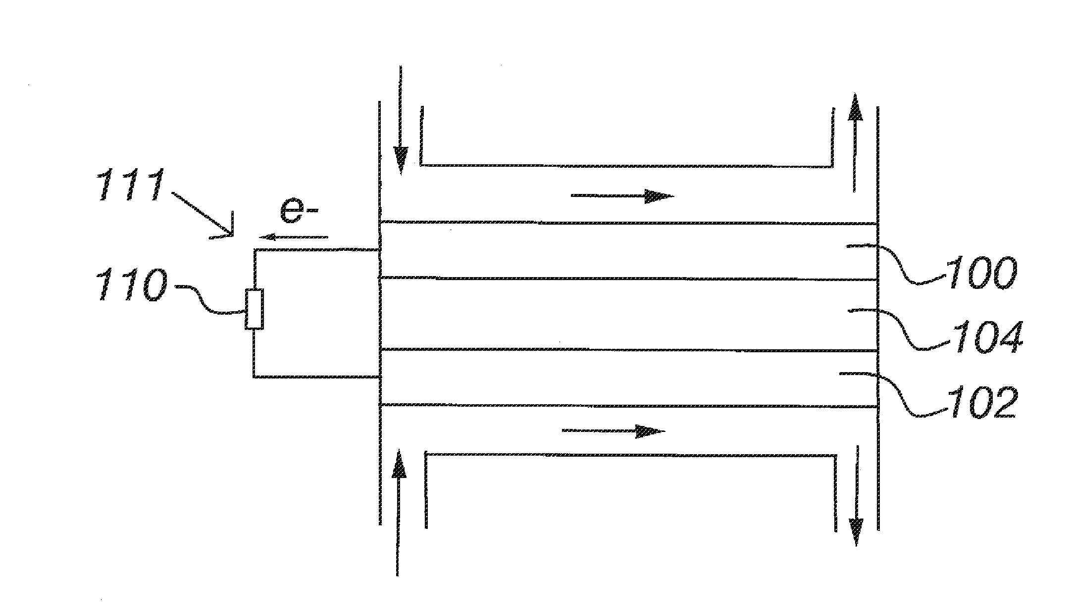
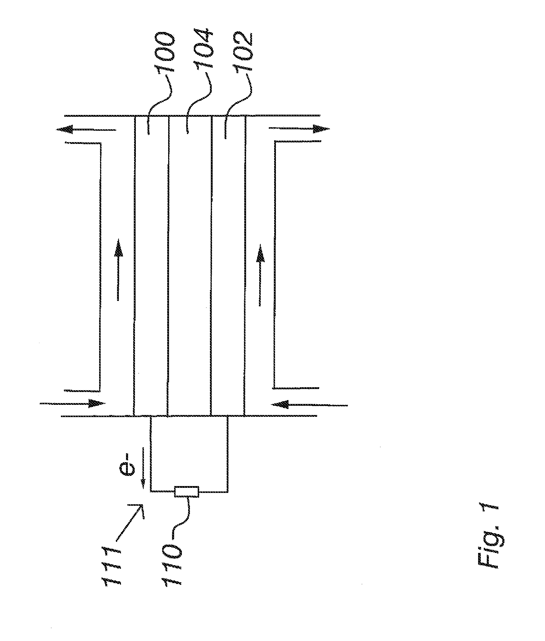
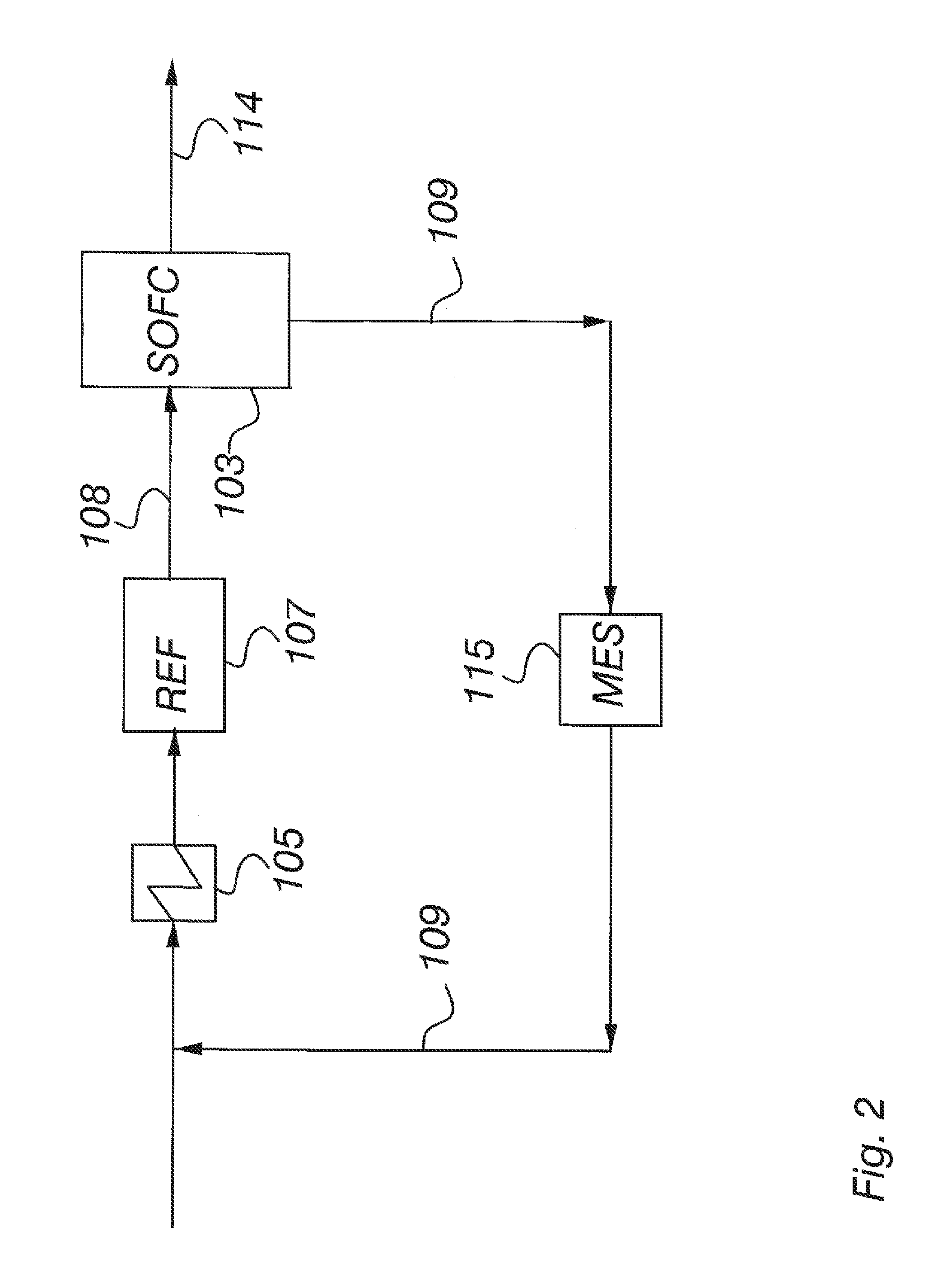
[0019]Exemplary embodiments provide a practical Oxygen-to-Carbon (O / C) relationship management in a fuel cell system by utilizing known system components. This can be achieved by an arrangement for controlling an Oxygen-to-Carbon (O / C) relationship in a fuel cell system for producing electricity with fuel cells, each fuel cell in the fuel cell system comprising an anode side, a cathode side and an electrolyte between the anode side and the cathode side. The fuel cell system comprises means for feeding gas used as fuel to the anode side, and means for recirculating part of the anode side gas. The arrangement for controlling an Oxygen-to-Carbon (O / C) relationship comprises means for providing water to the arrangement, at least one water pump for pumping the provided water to facilitate a water flow, means for evaporating water from said facilitated water flow for generating pressurized steam having at least the motive pressure for a steam jet-ejector, and said at least one steam jet-e...


PUM


Abstract

A fuel cell system arrangement is disclosed for controlling an Oxygen-to-Carbon (O/C) relationship by providing water to an anode side fuel recirculation, pumping the provided water to facilitate a water flow, and evaporating water from the facilitated water flow for generating pressurized steam having at least the motive pressure for a steam jet-ejector. The at least one steam jet-ejector can inject at least part of the steam to the fuel cell system, and entrain part of an essentially low pressure anode exhaust gas stream in the anode side gas recirculation and compress the gas mixture to an intermediate pressure of the fuel feed-in stream for controlling the Oxygen-to-Carbon (O/C) relationship in the fuel side of the fuel cell system.

Description

RELATED APPLICATION[0001]This application claims priority as a continuation application under 35 U.S.C. §120 to PCT / FI2010 / 050704, which was filed as an International Application on Sep. 14, 2010 designating the U.S., and which claims priority to Finnish Application 20096128 filed in Finland on Oct. 30, 2009. The entire contents of these applications are hereby incorporated by reference in their entireties.FIELD[0002]Due in part to environmental issues, new energy sources that are environmentally friendly and with good efficiency have been developed. Fuel cell devices are promising future energy conversion devices by which fuel, for example bio gas can be directly transformed to electricity via a chemical reaction in an environmentally friendly process.BACKGROUND INFORMATION[0003]An exemplary fuel cell, as presented in FIG. 1, includes an anode side 100 and a cathode side 102 and an electrolyte material 104 between them. In solid oxide fuel cells (SOFCs) oxygen is fed to the cathode...

Claims


Application Information

Patent Timeline
IPC IPC(8): H01M8/04H01M8/06
CPCH01M8/04097H01M8/0618Y02E60/50H01M8/12H01M8/0625F04F5/00H01M8/04298
Inventor HAKALA, TUOMAS
Owner CONVION OY
Why Eureka
Try Eureka