GNSS based control for dispensing material from vehicle

a technology for dispensing materials and vehicles, applied in vehicle position/course/altitude control, process and machine control, instruments, etc., can solve the problems of inability to accurately determine poi, less than precise production, and inability to take into account the actual curvature of terrain

Active Publication Date: 2012-08-23
AGJUNCTION
View PDF5 Cites 116 Cited by
  • Summary
  • Abstract
  • Description
  • Claims
  • Application Information

AI Technical Summary

Benefits of technology

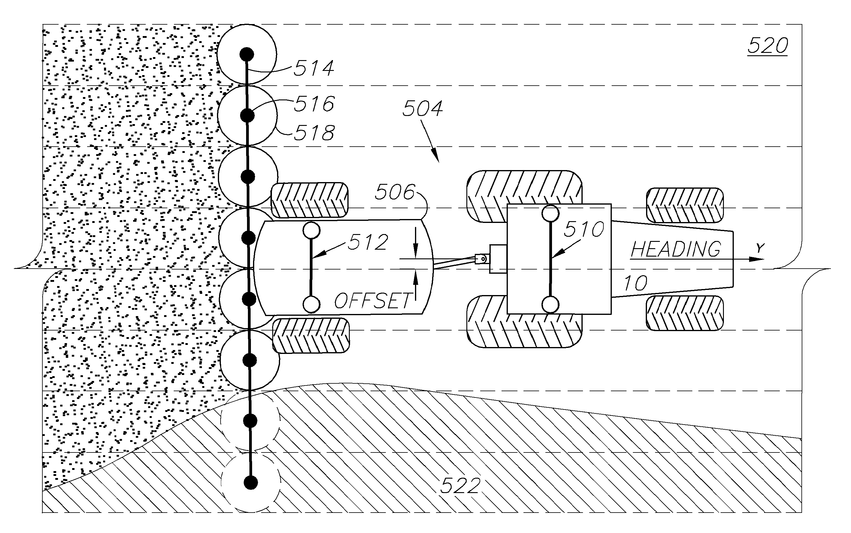
[0018]Areas to be sprayed are designated as spray zones while areas not to be sprayed are designated as exclusion zones. The spray zones and exclusion zones are separated by linear boundaries, which are surveyed, and coordinates of the boundaries are stored in the controller. The controller is a computer having data storage, data inputs and outputs, and controlled outputs connected to suitable drivers and/or relays to control particular processes or actions. When the spray vehicle

Problems solved by technology

However, in existing satellite positioning systems (SATPS) for guided parallel and contour swathing for precision farming, mining, and the like, the actual curvature of terrain may not be taken into account.
This results in a less than precise production because of the less than precise parallel or contour swathing.
However, if the tractor is on an inclined terrain with a variable tilt, which is often the case, the SATPS alone cannot determine the terrain tilt so the POI also cannot be determined.
This results in a guidance error because the POI is approximated by the point of reception (POR), and this approximation worsens as the terrain inclination increases.
This results in cross track position excursions relative to the vehicle ground track which would contaminate any attempt to guide to a defined field line or swath.
Systems using Doppler radar will encounter errors with the radar and latency.
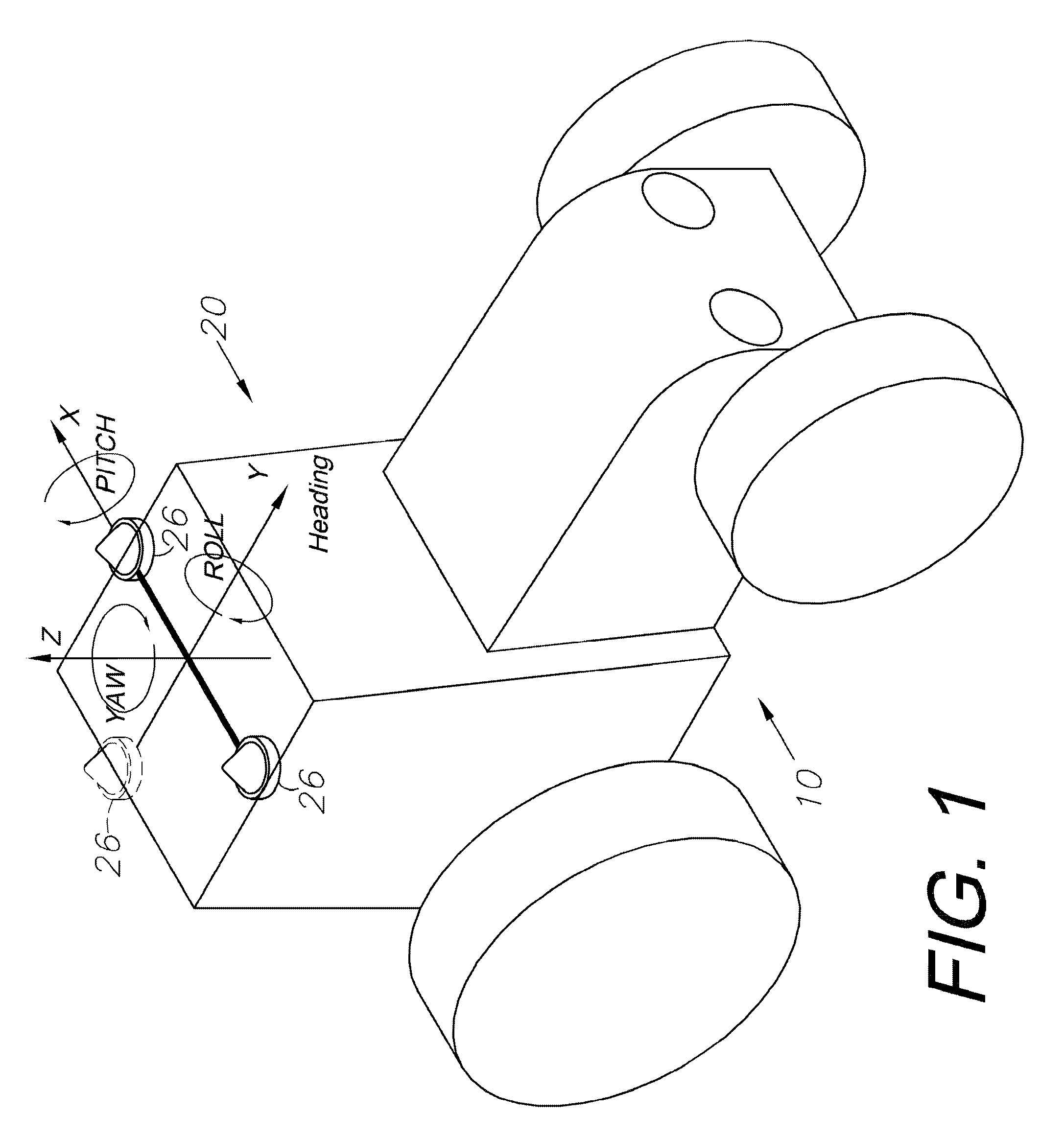
Similarly, gyroscopes, which may provide heading, roll, or pitch measurements, may be deployed as part of an inertial navigation package, but tend to encounter drift errors and biases and still require some external attitude measurements for gyroscope initialization and drift compensation.
G

Method used


Image

  • GNSS based control for dispensing material from vehicle
  • GNSS based control for dispensing material from vehicle
  • GNSS based control for dispensing material from vehicle

Examples


Embodiment Construction

[0059]As required, detailed embodiments of the present invention are disclosed herein; however, it is to be understood that the disclosed embodiments are merely exemplary of the invention, which may be embodied in various forms. Therefore, specific structural and functional details disclosed herein are not to be interpreted as limiting, but merely as a basis for the claims and as a representative basis for teaching one skilled in the art to variously employ the present invention in virtually any appropriately detailed structure.

I. GNSS Introduction

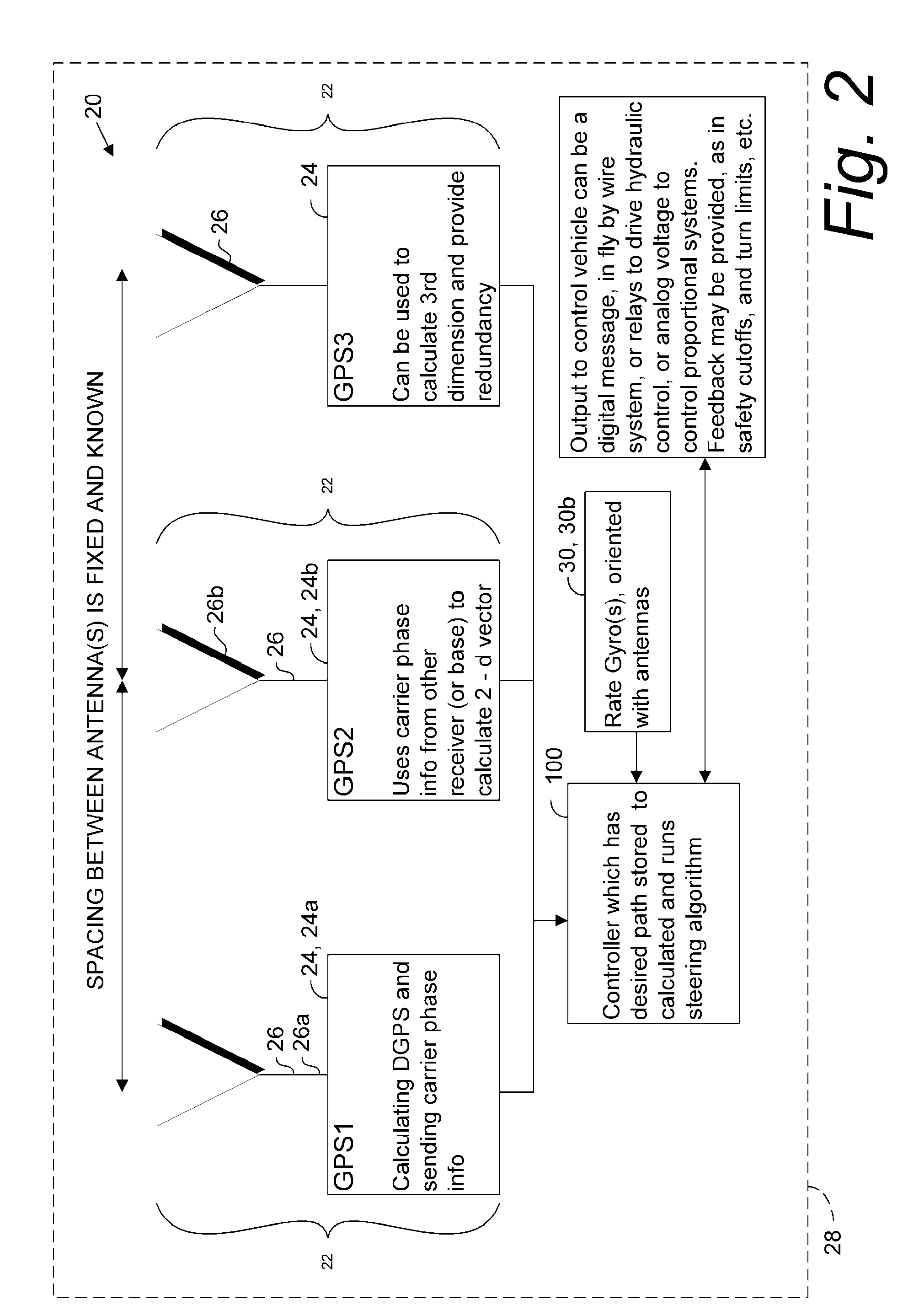
[0060]Global navigation satellite systems (GNSS) are broadly defined to include GPS (U.S.), Galileo (proposed), GLONASS (Russia), Beidou / Compass (China, proposed), IRNSS (India, proposed), QZSS (Japan, proposed) and other current and future positioning technology using signals from satellites, with or without augmentation from terrestrial sources. Inertial navigation systems (INS) include gyroscopic (gyro) sensors, accelerometers and simil...


PUM


Abstract

A spray control method employs a spray vehicle including a material tank, a pump communicating with the tank, and nozzles of a spray boom communicating with the pump. A GNSS receiver mounted on the vehicle and interfaced to a controller tracks its position in relation to stored position coordinates of field boundaries separating spray zones from spray exclusion zones. The tank is activated and deactivated by the controller to retain spray of the material within the spray zones and to prevent spray of the material in the exclusion zones, by processing an offset of the spray nozzles from the receiver, the spray range of the nozzles, spray turn-on and turn-off lag times, and the velocity of the spray vehicle, all in relation to the field boundaries. An alternative embodiment individually controls spray from the nozzles by using associated valves interfaced to the controller.

Description

CROSS-REFERENCE TO RELATED APPLICATIONS[0001]This application is a continuation-in-part of and claims the benefit of: U.S. patent application Ser. No. 12 / 355,776, filed Jan. 17, 2009; which is a continuation-in-part of Ser. No. 12 / 171,399, filed Jul. 11, 2008; which is a continuation-in-part of Ser. No. 10 / 804,758, filed Mar. 19, 2004, now U.S. Pat. No. 7,400,956 and a continuation-in-part of Ser. No. 10 / 828,745, filed Apr. 21, 2004, now abandoned which benefited from U.S. Provisional Patent Application Ser. No. 60 / 456,146, filed Mar. 20, 2003 and Ser. No. 60 / 464,756, filed Apr. 23, 2003. This application is also a continuation-in-part of U.S. patent application Ser. No. 12 / 750,429 filed Mar. 30, 2010; which is a continuation of U.S. patent application Ser. No. 11 / 184, 657, filed Jul. 19, 2005, now U.S. Pat. No. 7,689,354. The contents of all of the aforementioned applications and patents are incorporated by reference herein in their entireties.BACKGROUND OF THE INVENTION[0002]Movab...

Claims


Application Information

Patent Timeline
IPC IPC(8): G06F19/00
CPCA01B79/005G01C15/00G01S5/0063G01S19/04G05D2201/0201G01S19/54G05D1/0259G05D1/027G05D1/0278G01S19/14
Inventor MCCLURE, JOHN A.STICHTER, AARON C.
Owner AGJUNCTION
Why Eureka
Try Eureka