Fuel injection system for internal combustion engine

a fuel injection system and internal combustion engine technology, applied in the direction of electrical control, process and machine control, instruments, etc., can solve the problems of fuel injection system not working, actual pressure in the common rail overshoots the new target, and the difficulty in accurately and quickly adjusting the high-pressure pump in response, so as to avoid unnecessary pump operation and avoid unnecessary pressure-reducing valve operation

Active Publication Date: 2012-08-23
DENSO CORP
View PDF4 Cites 17 Cited by
  • Summary
  • Abstract
  • Description
  • Claims
  • Application Information

AI Technical Summary

Benefits of technology

[0017]The fuel injection system may also include a pressure-reducing valve which works to reduce the pressure of the fuel in the accumulator when the required quantity of the fuel has a negative value. The fuel injection system is, therefore, permitted to activate only either of the pump or the pressure-reducing valve, thus avoiding unnecessary operations of the pump.
[0018]When the required quantity of the fuel has a value greater than or equal to zero, the pump controlling task instructs the pump to feed the fuel to the accumulator. The fuel injection system is, therefore, permitted to activate only either of the pump or the pressure-reducing valve, thus avoiding unnecessary operations of the pressure-reducing valve.

Problems solved by technology

The fuel injection system, as taught in the above publication, starts to control the operation of the high-pressure pump after a deviation of the pressure in the common rail from the target pressure occurs and, thus, faces a difficulty in controlling the high-pressure pump precisely and quickly in response to the pressure deviation.
This may result in a high probability that when the target pressure changes with a change in operating condition of the engine, the actual pressure in the common rail overshoots the new target pressure or hunts around it.
Specifically, unlike the prior art system, as discussed in the introductory part of this application, the fuel injection system does not work to control the operation of the pump so as to compensate for the pressure difference between the target pressure and the actual pressure in the accumulator, but is engineered to determine the quantity of fuel required to bring the pressure in the accumulator into agreement with the target pressure and then drive the pump to feed the fuel by the determined quantity.
If a desired degree of ability of the pump is not obtained due to a production tolerance thereof or an error in calculating the required quantity of the fuel, a difference between the required quantity and the actual quantity will occur.

Method used


Image

  • Fuel injection system for internal combustion engine
  • Fuel injection system for internal combustion engine
  • Fuel injection system for internal combustion engine

Examples


Embodiment Construction

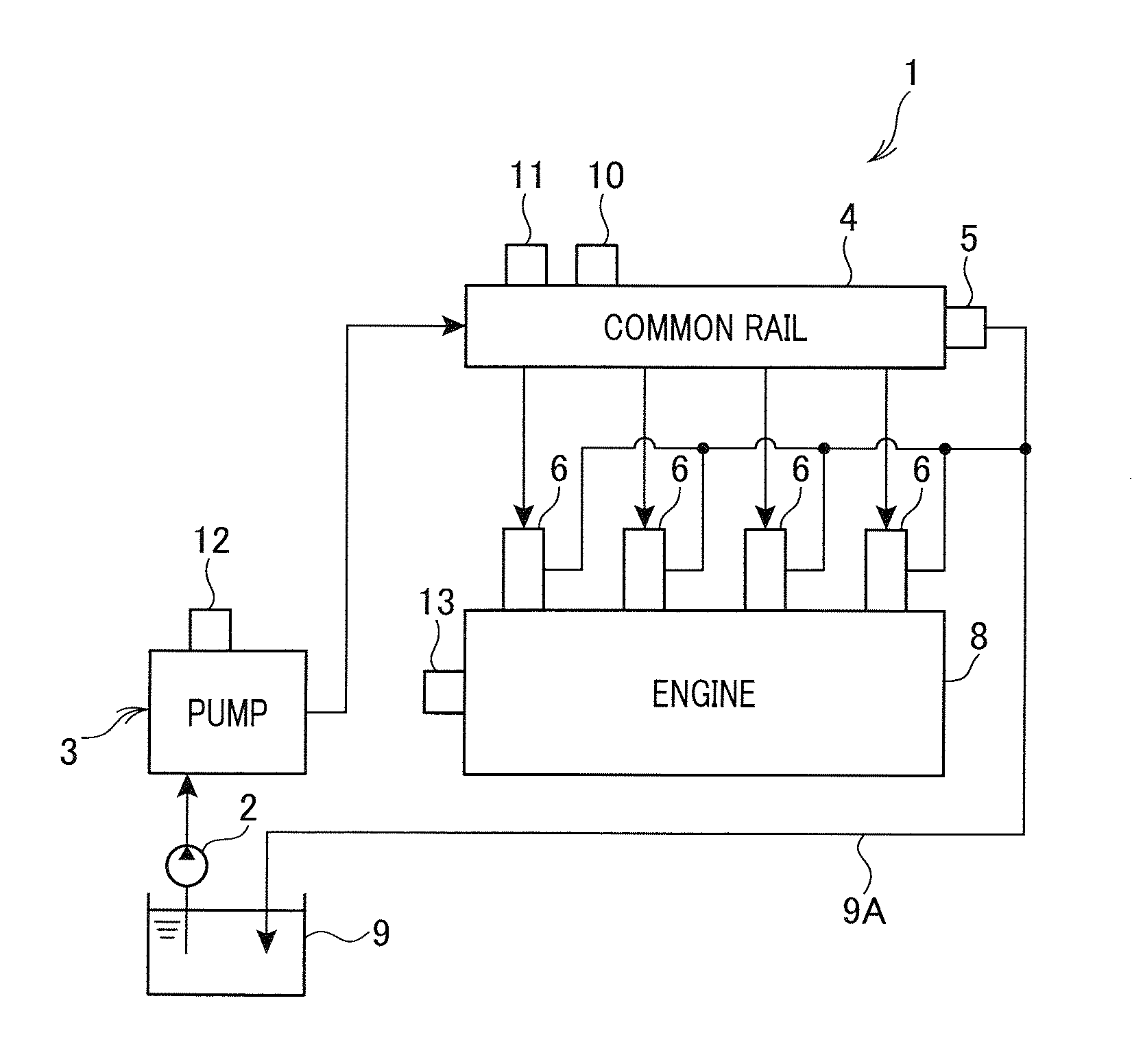
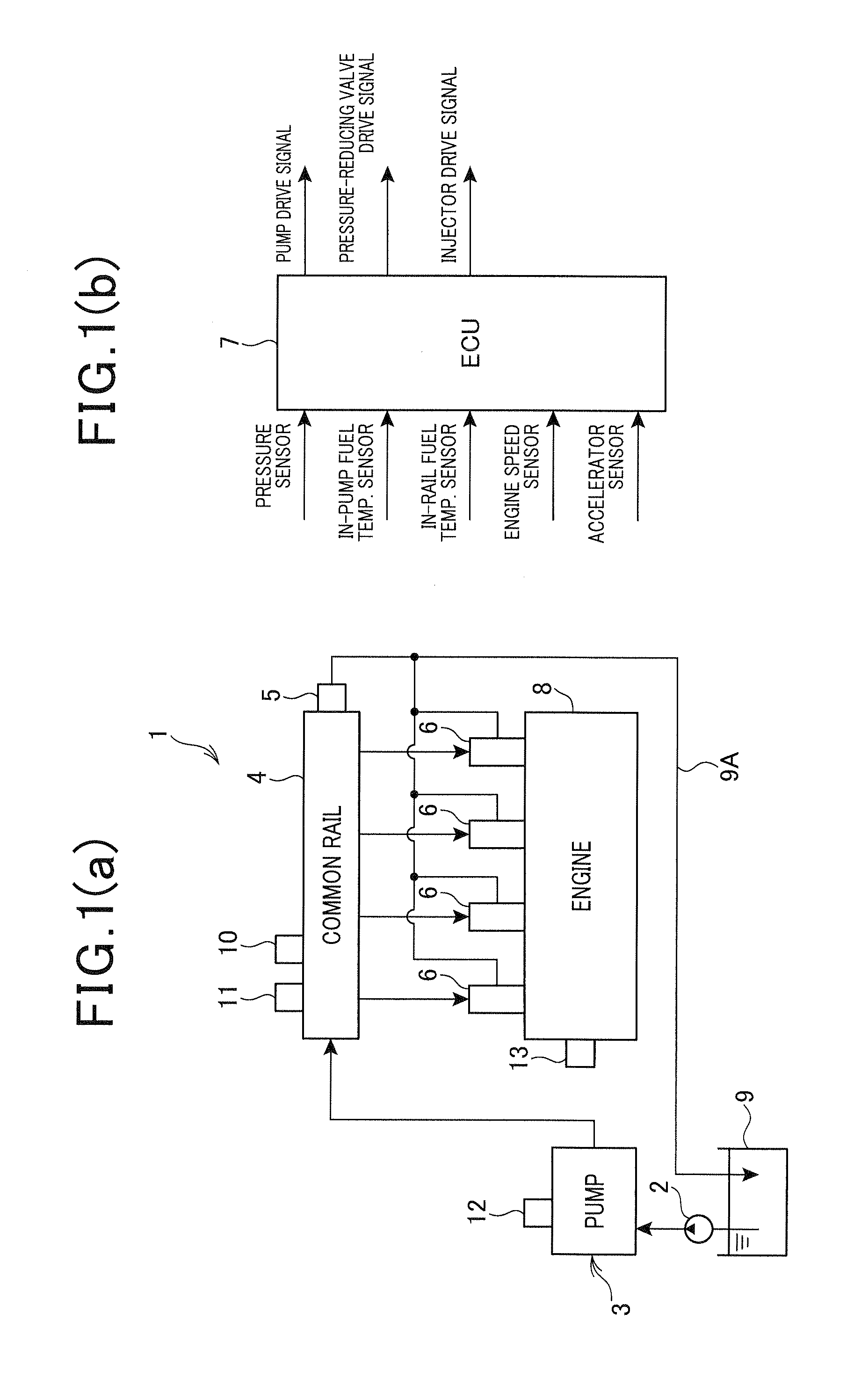
[0028]Referring to the drawings, wherein like reference numbers refer to like parts in several views, particularly to FIGS. 1(a) and 1(b), there is shown a fuel injection system 1 according to an embodiment of the invention which is designed control spraying of fuel to a four-cycle internal combustion diesel engine 8 for automotive vehicles.

1 Structure of Fuel Injection System

[0029]The fuel injection system 1 is of a common rail type and equipped with a feed pump 2, a high-pressure pump 3, a common rail 4 serving as a fuel accumulator, a pressure-reducing valve 5, fuel injectors 6, and an electronic control unit (ECU) 7 which drives the fuel injectors 6 (i.e., fuel injection valves) installed one in each of four cylinders of the diesel engine 8.

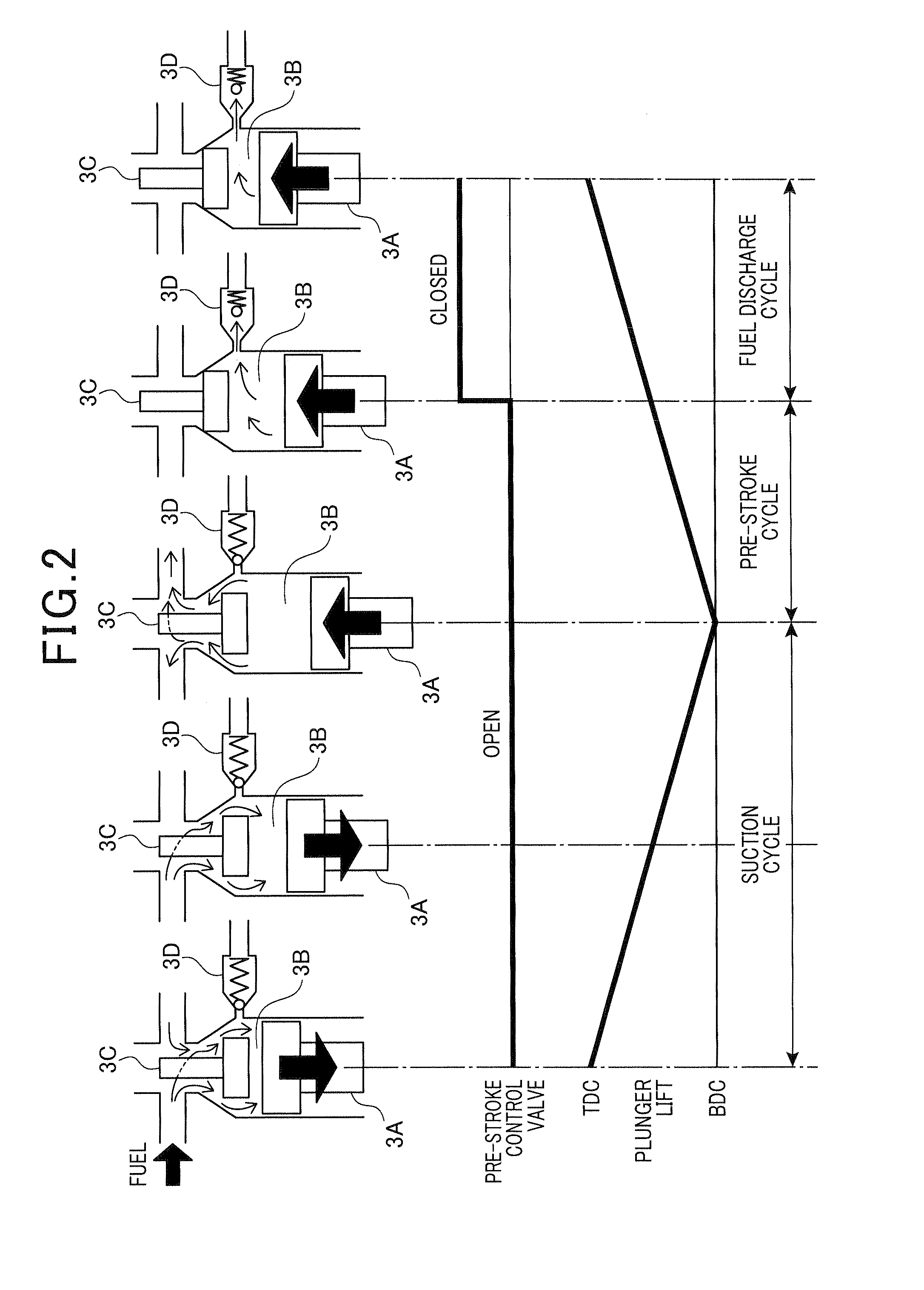
[0030]The feed pump 2 sucks fuel from a fuel tank 9 and feeds it to the high-pressure pump 3. The high-pressure pump 3 is, as illustrated in FIG. 2, equipped with a plunger 3A which is driven by an output of the engine 8 so that it reciprocat...


PUM


Abstract

A fuel injection system for an internal combustion engine is provided which calculates the quantity of fuel required to bring the pressure in a fuel accumulator into agreement with a target pressure and then control an operation of a high-pressure pump based on the required quantity. Even in the absence of a change in pressure in the accumulator, the system controls the high-pressure pump based on the required quantity. Specifically, the system calculates a feedback fuel quantity required to compensate for a difference between the required quantity and a quantity of the fuel actually supplied to the accumulator, in other words, leans such a quantity difference to correct the required quantity, thus resulting in an enhanced response of the system to control the high-pressure pump to a change in pressure in the accumulator.

Description

CROSS REFERENCE TO RELATED DOCUMENT[0001]The present application claims the benefit of priority of Japanese Patent Application No. 2011-33536 filed on Feb. 18, 2011, the disclosure of which is incorporated herein by reference.BACKGROUND[0002]1. Technical Field[0003]The present invention relates generally to a fuel injection system for internal combustion engines, and particularly to a common rail fuel injection system for diesel engines which may be employed in automotive vehicles.[0004]2. Background Art[0005]The common rail fuel injection system is mostly employed with diesel internal combustion engines for automotive vehicles. Specifically, the common rail fuel injection system is equipped with a high-pressure pump, a common rail, and fuel injectors. The high-pressure pump works to pressurize fuel, as fed from a fuel tank, and supplies it to the common rail. The common rail stores the fuel at a controlled pressure. The fuel injectors spray the fuel, as supplied from the common rai...

Claims


Application Information

Patent Timeline
Patent Type & Authority Applications(United States)
IPC IPC(8): F02D41/30
CPCY02T10/44F02D41/2096F02D41/3845F02D2200/0606F02D41/406F02D2200/0602F02D41/3863Y02T10/40
Inventor SUGIYAMA, KOUICHIISHIZUKA, KOJI
Owner DENSO CORP
Why Eureka
Try Eureka