Method and System for Cleaning a Pond

Active Publication Date: 2012-08-30
POND MOWER
View PDF4 Cites 29 Cited by
  • Summary
  • Abstract
  • Description
  • Claims
  • Application Information

AI Technical Summary

Benefits of technology

[0043]One aspect of certain embodiments of the present invention include a bagging mechanism that permits an operator to remove larger debris from the pond without having such material suctioned completely through an extended hose that runs outside the pond. Instead, in one embodiment, the bagging mechanism is submersed in the pond and the bagging activity occurs at least partially underwater. In such a manner, the difficulties in handling leaves and larger debris, including the wear and tear on impeller mechanisms of vacuuming and suctioning units, is reduced. In a particular embodiment, a diaper genie-type device is employed at about the suction end closest to the pond bottom, used in association with special bagging material that is porous enough to permit large debris to be captured inside, while permitting a desirable amount of water and other smaller debris to pass therethrough. As shown in the Figures, the suction end can be designed to include a sealing mechanism for accumulated debris that is suctioned from the pond. Such sealing mechanism can include a storage container having a body and a storage film cartridge adapted to be positi

Problems solved by technology

Neither of these extremes is sufficient for a residential pond owner or for a pond servicing service where routine and periodic servicing of ponds of 8 feet wide to about 1 acre is involved.
Problems also exist in the use of such devices, including difficulties with respect to access to deeper portions of ponds, vacuum suction loss due to long tubes or pipes from the motor to the debris at the bottom of the pond, efficiencies of pumping action and ability to distribute and/or filter debris after removal from the pond; return of dirty water back to a pond, etc.
Even other designs that employ submergible vacuums suffer from various deficiencies, including the absence of any s

Method used


Image

  • Method and System for Cleaning a Pond
  • Method and System for Cleaning a Pond
  • Method and System for Cleaning a Pond

Examples


Embodiment Construction

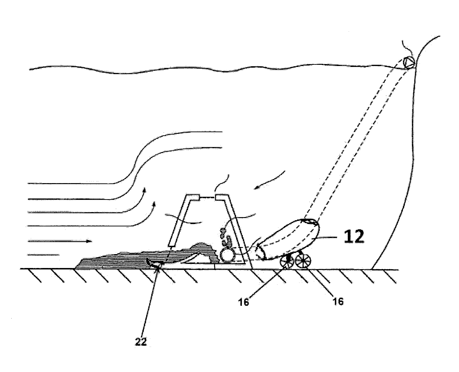
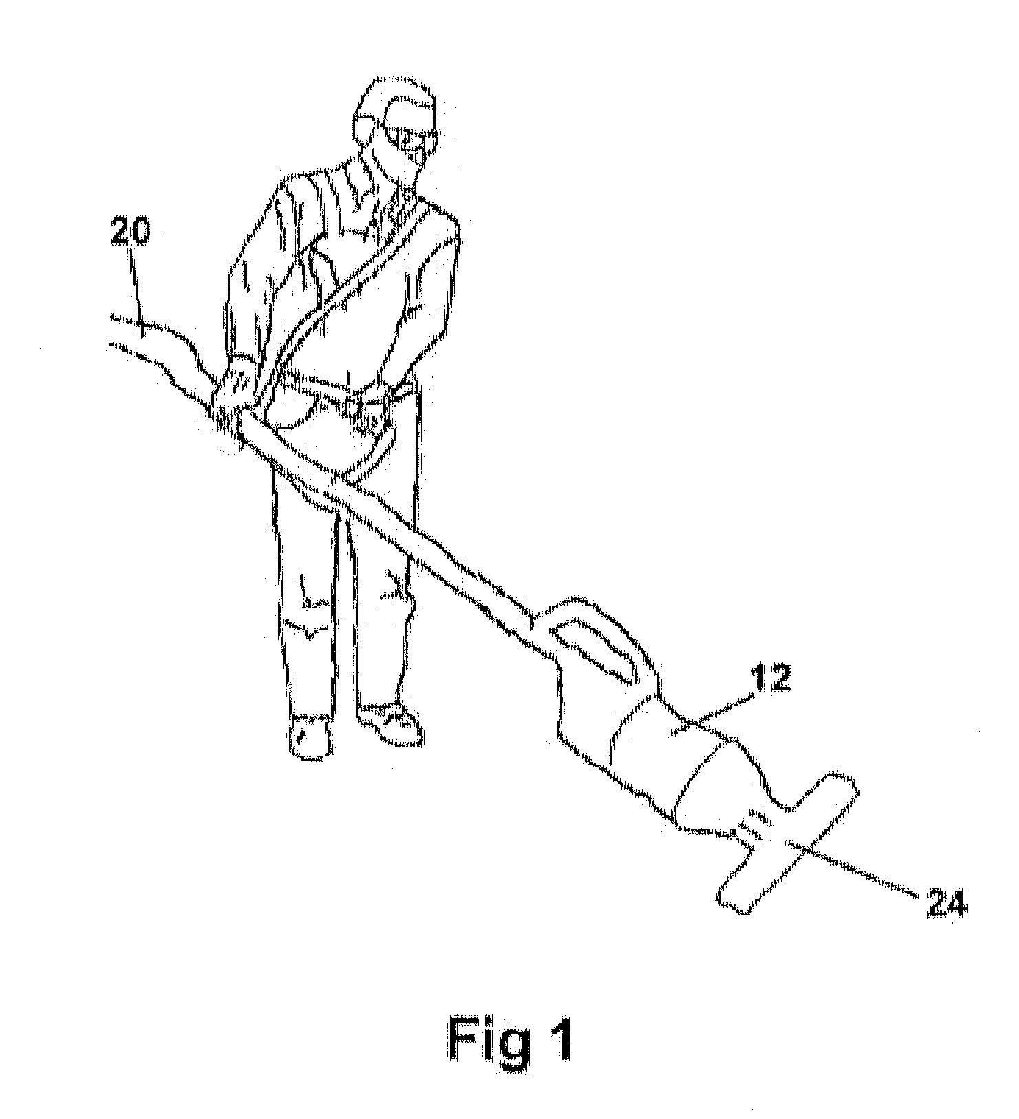
[0075]FIG. 1 illustrates the apparatus of the invention 10 in a working environment for removing a layer of sediment which has settled on the bottom of a pond. The apparatus comprises a frame with a first end and a second end. A chamber with a first end and a second end is positioned proximate the first end of the frame. The chamber provides a conduit for conveying slurry to the input port of a pump and adjustment of the size of apertures can be made to adjust the ratio of sediment to water removed from the bottom of the pond.

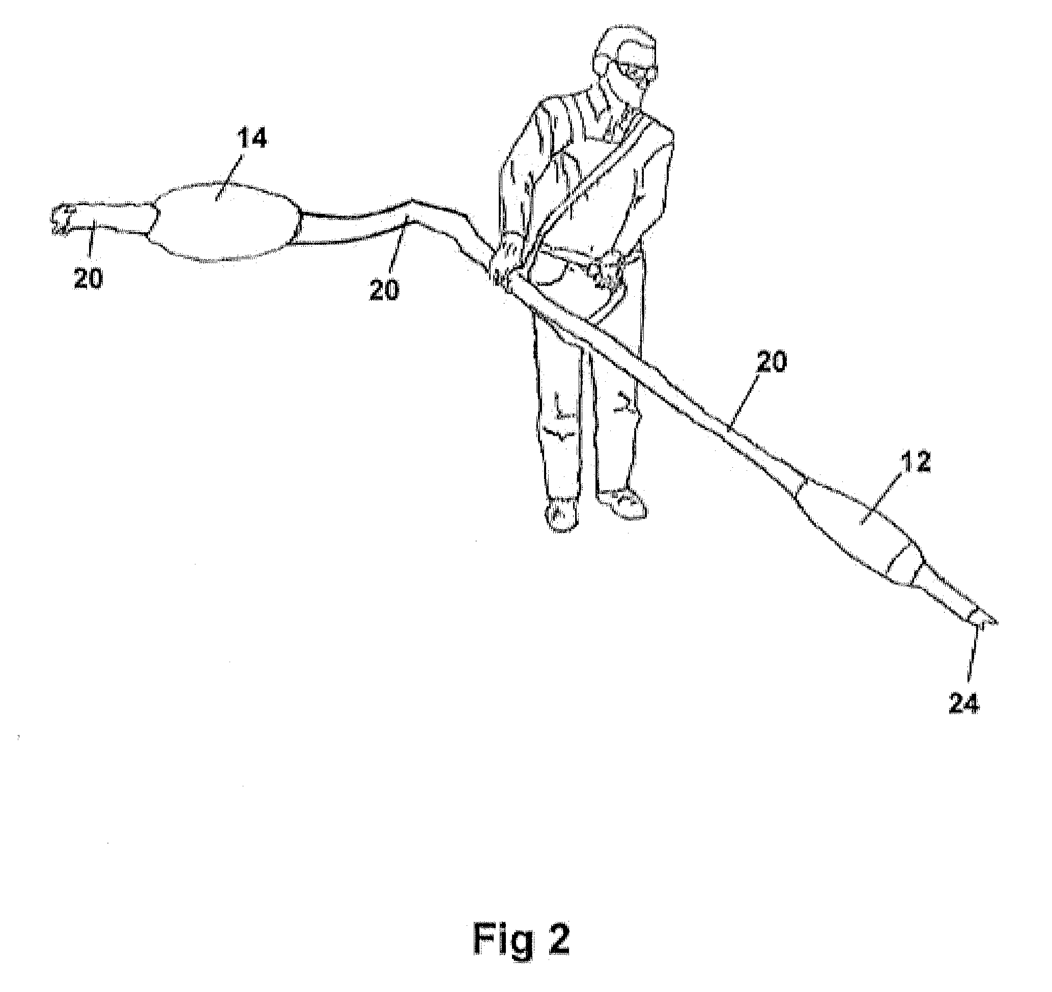
[0076]Preferably, a single wheel supports the vacuum unit and such unit is electrically powered via a long cord. The vacuum unit may include an inlet port and an outlet port. Preferably, the input port is in fluid communication with a chamber. A flexible conduit is in fluid communication with the second end of the chamber and with open conduit which extends above the level of pond.

[0077]Various patents and patent publications are hereby incorporated by referenc...


PUM


Abstract

The present invention is generally directed to a system, device and method for removing a layer of sediment formed on the bottom of a pond. A submersible vacuum unit associated with in-line import and export sections made from at least 2 inch diameter tubing is supported by a single ski or wheel that is in contact with the pond bottom surface, with a flexible hose connected to the export and directed outside the pond for disposal or filtering of suctioned water. In certain embodiments, leaf /debris bagging mechanisms or mulching mechanisms are employed to facilitate removal of large debris from pond bottoms, while fine silt material is contained in a region and suctioned off the bottom surface.

Description

RELATED APPLICATION[0001]This application claims priority from U.S. Provisional Patent Application No. 61 / 446,282 filed Feb. 24, 2011 and U.S. Provisional Patent Application No. 61 / 471,506 filed on Apr. 4, 2011. The entire disclosure of the prior applications is considered to be part of the disclosure of the accompanying application and is hereby incorporated by reference.FIELD OF THE INVENTION[0002]The present invention relates to an apparatus and method for cleaning sediment from a pond, and more particularly for removing sediment from the bottom of a pond using a powered vacuum device.BACKGROUND OF THE INVENTION[0003]Numerous devices for removing sediment from ponds, lakes, streams, lagoons, and the like are known in the prior art. These vary from large trucks fitted with huge pumps and vacuums, to garden hose devices purportedly capable of creating suction sufficient to remove silt and debris from the bottom of a pond. Neither of these extremes is sufficient for a residential po...

Claims


Application Information

Patent Timeline
IPC IPC(8): E04H4/16C02F1/00
CPCC02F2103/007C02F2201/008E04H4/1636C02F2303/24C02F1/001C02F2301/08
Inventor KOVARIK, JOSEPH E.FRANEK, JEFF
Owner POND MOWER
Why Eureka
Try Eureka