Soldering jig

Inactive Publication Date: 2012-08-30
DONGGUK UNIV IND ACADEMIC COOPERATION FOUND
View PDF7 Cites 3 Cited by
  • Summary
  • Abstract
  • Description
  • Claims
  • Application Information

AI Technical Summary

Benefits of technology

[0009]An embodiment of the present invention provides a soldering jig that can ap

Problems solved by technology

The lid needs to be joined with the brazed stud and ceramic ring by use of a solder, such as Au—Sn or Ag—Sn, because a joining process such as

Method used


Image

  • Soldering jig
  • Soldering jig
  • Soldering jig

Examples


Embodiment Construction

[0023]Hereinafter, an embodiment of the present invention will be described with reference to the accompanying drawings.

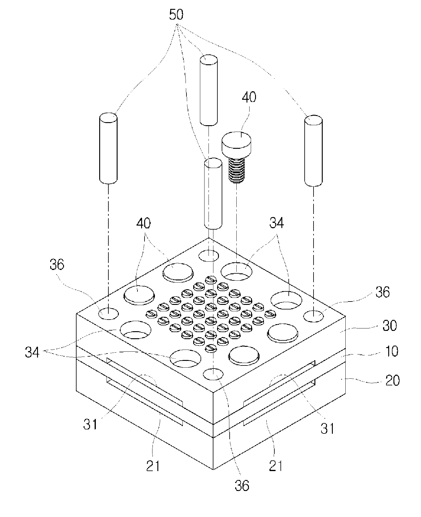
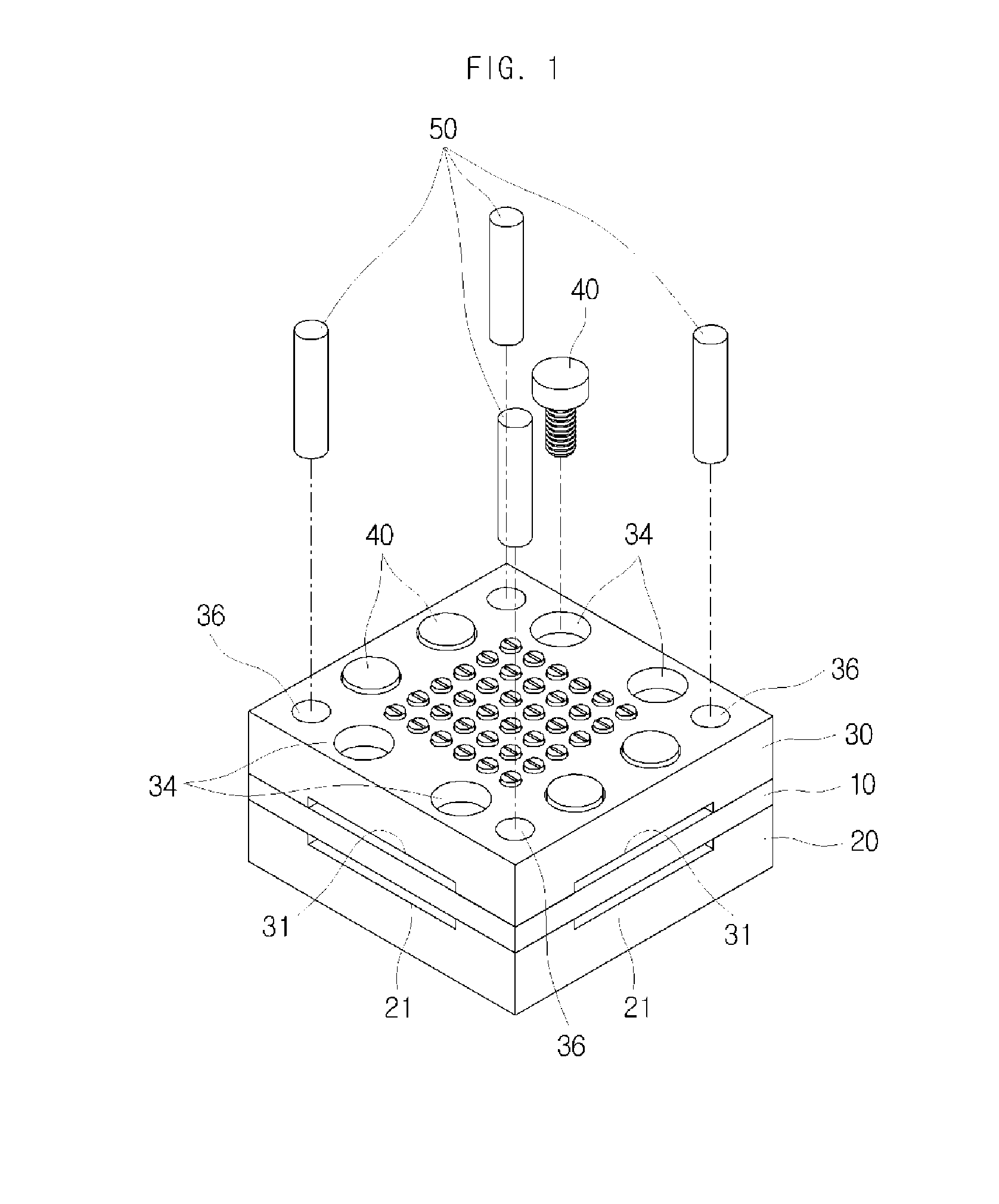
[0024]FIG. 1 is a perspective view showing a soldering jig in accordance with an embodiment of the present invention, and FIG. 2 is a cross-sectional view showing the soldering jig in accordance with an embodiment of the present invention.

[0025]Referring to FIGS. 1 and 2, the soldering jig includes a mounting block 10, a first cover block 20 and a second cover block 30.

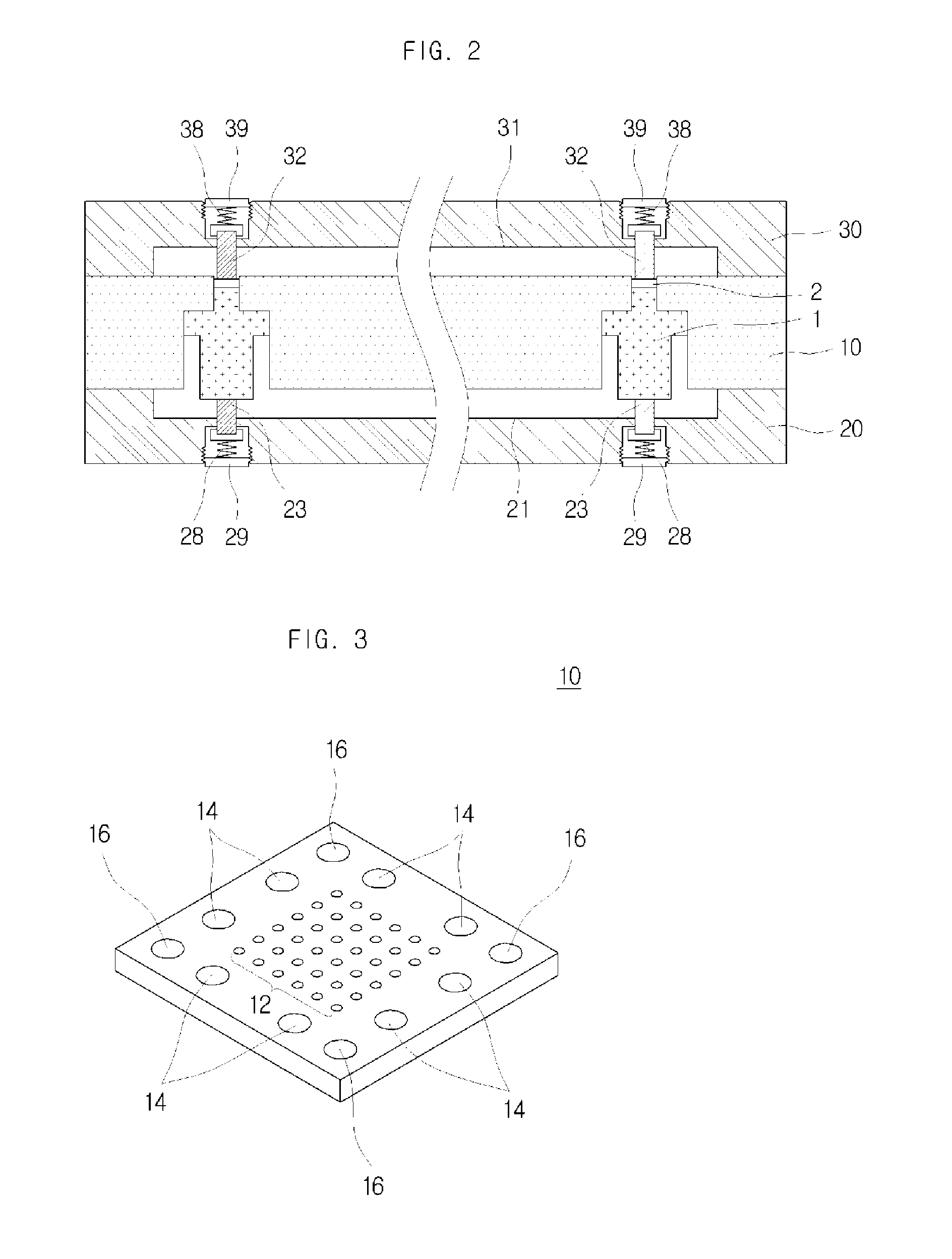
[0026]The mounting block 10 is a portion where a plurality of soldered objects 1, 2 are accommodated during a soldering process. Such a mounting block will be described in detail with reference to FIG. 3.

[0027]The first cover block 20 supports the plurality of soldered objects 1, 2 on one surface of the mounting block 10 during the soldering process. For this, the first cover block 20 is coupled to the one surface of the mounting block 10 and has a support part 22 that supports the plurality of solde...


PUM


Abstract

A soldering jig is disclosed. The soldering jig in accordance with an embodiment of the present invention includes: a mounting block having a plurality of accommodation holes penetrating from one surface to the other surface thereof, a plurality of soldered objects being accommodated in the plurality of accommodation holes; a first cover block coupled to one surface of the mounting block and having a support part configured to support the plurality of soldered objects accommodated in the plurality of accommodation holes; and a second cover block coupled to the other surface of the mounting block and having a plurality of pressing protrusions protruded to face the plurality of accommodation holes, respectively, to elastically support the plurality of soldered objects. Accordingly, a Gunn diode package that is soldered in a uniform quality can be obtained by maintaining a uniform pressure and heat transfer to the soldered objects in a soldering process.

Description

CROSS-REFERENCE TO RELATED APPLICATIONS[0001]This application is a continuation of PCT / KR / 2010 / 007297 filed Oct. 22, 2010, which claims the benefit of Korean Patent Application No. 10-2009-0108186, filed with the Korean Intellectual Property Office on Nov. 10, 2009 and Korean Patent Application No. 10-2009-0114800, filed with the Korean Intellectual Property Office on Nov. 25, 2009, the disclosures of which are incorporated herein by reference in entirety.BACKGROUND[0002]1. Technical Field[0003]The present invention relates to a soldering jig.[0004]2. Background Art[0005]With an increasing demand for millimeter wave FMCW radar sensors, the performance of the voltage controlled oscillator (VCO), which is an important component of the FMCW radar sensor, has been increasingly improved. Particularly, there have been a large number of studies on Gunn diode, which is an oscillation device of the VCO.[0006]Importance for the production of the Gunn diode for use in the VCO is the package te...

Claims


Application Information

Patent Timeline
IPC IPC(8): B23K3/00
CPCB23K3/087H01Q21/0087
Inventor RHEE, JIN KOO
Owner DONGGUK UNIV IND ACADEMIC COOPERATION FOUND
Why Eureka
Try Eureka