Light-emitting layer and light-emitting element

a light-emitting layer and light-emitting element technology, applied in the field of carrier-injection organic electroluminescence, can solve the problems of poor hole-transport property of the host, deficiency of organic light-emitting material molecules, and poor transporting property of the other, so as to improve quantum efficiency and reduce the probability of thermal deactivation, the effect of improving the probability of the transition of the triplet excited sta

Active Publication Date: 2012-08-30
SEMICON ENERGY LAB CO LTD
View PDF10 Cites 124 Cited by
  • Summary
  • Abstract
  • Description
  • Claims
  • Application Information

AI Technical Summary

Benefits of technology

[0020]The singlet excited state and the triplet excited state of the host are transferred to the triplet excited state of the organic light-emitting material, and the organic light-emitting material returns to the ground state, whereby light emission occurs. In general, energy level in the triplet excited state of the host is set to be higher than energy level in the triplet excited state of the organic light-emitting material. This is in order to prevent transition of the triplet excited state of the organic light-emitting material to the triplet excited state of the host. Accordingly, the difference between the energy level in the triplet excited state of the host and the energy level in the triplet excited state of the organic light-emitting material is preferably larger for this purpose.
[0035]On the other hand, in one embodiment of the present invention, by provision of the layer which contains the organic light-emitting material molecule and has a thickness of one molecule to five molecules, which can emit light (phosphorescence) through the transition from the triplet excited state to the ground state at an interface between the layer of the n-type organic material and the layer of the p-type organic material, quantum efficiency can be increased.
[0036]In the above-described structure, the n-type organic material and the p-type organic material are isolated from each other; therefore, the probability of generation of an exciplex therebetween is decreased, and thus electrons passing through the layer of the n-type organic material and holes passing through the layer of the p-type organic material are injected to the organic light-emitting material molecule, so that the organic light-emitting material molecule is brought into the singlet excited state or the triplet excited state.
[0044]However, as described above, in a structure in which an n-type organic material and a p-type organic material are isolated from each other by a layer which contains an organic light-emitting material molecule, even if the organic light-emitting material molecule interposed therebetween is in an excited state, a probability that electrons passing through the n-type organic material are injected to the p-type organic material or a probability that holes passing through the p-type organic material are injected to the n-type organic material is extremely low. Accordingly, a probability of thermal deactivation is decreased, so that quantum efficiency can be improved.
[0045]Note that in this state, electrons remain in the layer of the n-type organic material (on the cathode side) and holes remains in the layer of the p-type organic material (on the anode side), and they cancel external voltage to some degree, so that current supplied to the organic light-emitting material is automatically controlled. In other words, overcurrent can be prevented from being supplied to the organic light-emitting material, the n-type organic material or the p-type organic material, which prevents the organic light-emitting material, the n-type organic material or the p-type organic material from deteriorating.
[0046]Further, in one embodiment of the present invention, electrons are injected from the n-type organic material to the LUMO of the organic light-emitting material, and holes are injected from the p-type organic material to the HOMO of the organic light-emitting material, and as described later, even a large difference between energy level in the triplet excited state of the n-type organic material (or the p-type organic material) and energy level in the triplet excited state of the organic light-emitting material, does not result in energy loss.

Problems solved by technology

However, a substance serving as a host normally has a high transporting property for either electrons or holes but has a poor transporting property for the other.
For example, in the case where a host is a material having an excellent electron-transport property, the hole-transport property of the host is relatively poor.
On the other hand, holes (or cations) are localized in the vicinity of the anode, because holes have low mobility.
If light emission occurs in a localized portion as mentioned above, the organic light-emitting material molecules in a portion where light emission does not occur are not used at all, whereas the organic light-emitting material molecules in a portion where light emission occurs constantly repeatedly undergo excitation and light emission, which may lead to a situation where the portion where light emission occurs is deficient in the organic light-emitting material molecules.
Such host molecules cause a decrease in light emission efficiency.

Method used


Image

  • Light-emitting layer and light-emitting element
  • Light-emitting layer and light-emitting element
  • Light-emitting layer and light-emitting element

Examples


embodiment 1

[0055]In this embodiment, examples of an n-type organic material, a p-type organic material, and an organic light-emitting material, which can be used in one embodiment of the present invention, will be described. FIG. 3A shows a structural formula of 2-[3-(dibenzothiophen-4-yl)phenyl]dibenzo[f,h]quinoxaline (abbreviation: 2mDBTPDBq-II) as an example of the n-type organic material.

[0056]In general, when a heteroatom (an atom having higher electronegativity than carbon), such as a nitrogen atom, is introduced to constituent atoms of a six-membered aromatic ring such as a benzene ring, the heteroatom attracts a π electron on the ring and the aromatic ring tends to be deficient in electrons. Accordingly, this portion is likely to trap electrons. Heteroaromatic compounds comprising six-membered rings generally tend to serve as n-type organic materials.

[0057]Note that the LUMO level and the HOMO level of 2mDBTPDBq-II are −2.78 eV and −5.88 eV, respectively, and an energy difference betwe...

embodiment 2

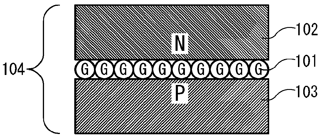
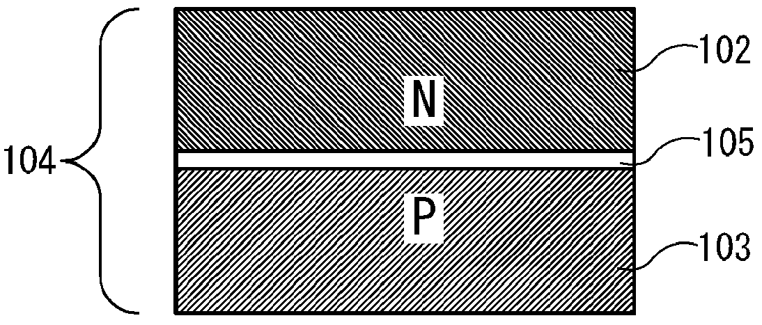
[0068]In this embodiment, a light-emitting mechanism of one embodiment of the present invention will be described with reference to FIGS. 4A to 4C. FIG. 4A shows a state in which electrons and holes injected from a cathode and an anode pass through the layer 102 of the n-type organic material and the layer 103 of the p-type organic material, respectively, and approach a monomolecular film of an organic light-emitting material (the organic light-emitting material molecule 101). Here, a left molecule of molecules included in the layer 102 of the n-type organic material is an anion, and a right molecule of molecules included in the layer 103 of the p-type organic material is a cation.

[0069]The relation between the LUMO level En (eV) of the n-type organic material and the LUMO level Ea (eV) of the organic light-emitting material is preferably En−0.5


PUM


Abstract

To provide a highly efficient organic light-emitting element. An extremely thin layer (a monomolecular film or the like) containing an organic light-emitting material such as an iridium complex is provided between a layer of an n-type organic material (an organic material having a high electron-transport property) and a layer of a p-type organic material (an organic material having a high hole-transport property). In a structure described above, in a layer of the organic light-emitting material, electrons are injected from the LUMO of the n-type organic material to the LUMO of the organic light-emitting material, and holes are injected from the HOMO of the p-type organic material to the HOMO of the organic light-emitting material, whereby the organic light-emitting material is brought into an excited state and emits light.

Description

BACKGROUND OF THE INVENTION[0001]1. Field of the Invention[0002]The present invention relates to carrier-injection organic electroluminescence (EL).[0003]2. Description of the Related Art[0004]Products to which a carrier-injection organic EL light-emitting phenomenon is applied are being put to practical use (for example, see Patent Document 1). There are generally two excited states a light-emitting material can be in, which are a singlet excited state and a triplet excited state, and the former is considered to be probabilistically about one-third of the latter.[0005]The ground state of a light-emitting material is a singlet state, and for ordinary organic molecules, the transition from the singlet excited state to the ground state is possible, but the transition from the triplet excited state to the ground state is forbidden. In other words, although light emission can be obtained through the transition from the singlet excited state to the ground state, in many cases, transition...

Claims


Application Information

Patent Timeline
Patent Type & Authority Applications(United States)
IPC IPC(8): H01L51/52B82Y20/00
CPCB82Y20/00H01L2251/558H01L2251/552H01L51/5012H10K50/11H10K2101/30H10K2102/351
Inventor TAKEMURA, YASUHIKOYAMAZAKI, SHUNPEI
Owner SEMICON ENERGY LAB CO LTD
Why Eureka
Try Eureka