Method for forming a decorative coating, a coating, and uses of the same

a technology of decorative coatings and coatings, applied in the direction of superimposed coating processes, instruments, natural mineral layered products, etc., can solve the problems of poor uniformity and conformation of the known methods of coating non-planar surfaces and substrates with complex shapes, inability to achieve the desired color or appearance, and inability to uniformly and uniformly coat complex three-dimensional objects. uniform and homogeneous coating of non-planar surfaces and substrates, etc., to achieve accurate control of film thickness, accurate control

Inactive Publication Date: 2012-08-30
BENEQ OY
View PDF2 Cites 3 Cited by
  • Summary
  • Abstract
  • Description
  • Claims
  • Application Information

AI Technical Summary

Benefits of technology

[0033]As each exposure of the surface of the substrate to a chemical results in a portion of the chemical being adsorbed onto the surface of the substrate, the number of how many times the surface of the substrate is exposed to the chemicals can be utilized in some embodiments of the invention to control the thickness of the film. These methods of forming a film on a substrate therefore enable very accurately controlling the thickness of the film. Hence, the total absorption of light in the film, and therefore th

Problems solved by technology

Otherwise a targeted color or appearance may not be achieved and/or the appearance may strongly depend on a position on the surface.
A shortcoming in the methods of the prior art to fabricate a decorative coating is that surfaces of complex three dimensional (3D) objects can not be uniformly or conformally coated with the known methods.
A problem with these coating methods is their poor ability to uniformly and homogeneously coat non-plana

Method used


Image

  • Method for forming a decorative coating, a coating, and uses of the same
  • Method for forming a decorative coating, a coating, and uses of the same
  • Method for forming a decorative coating, a coating, and uses of the same

Examples


example 1

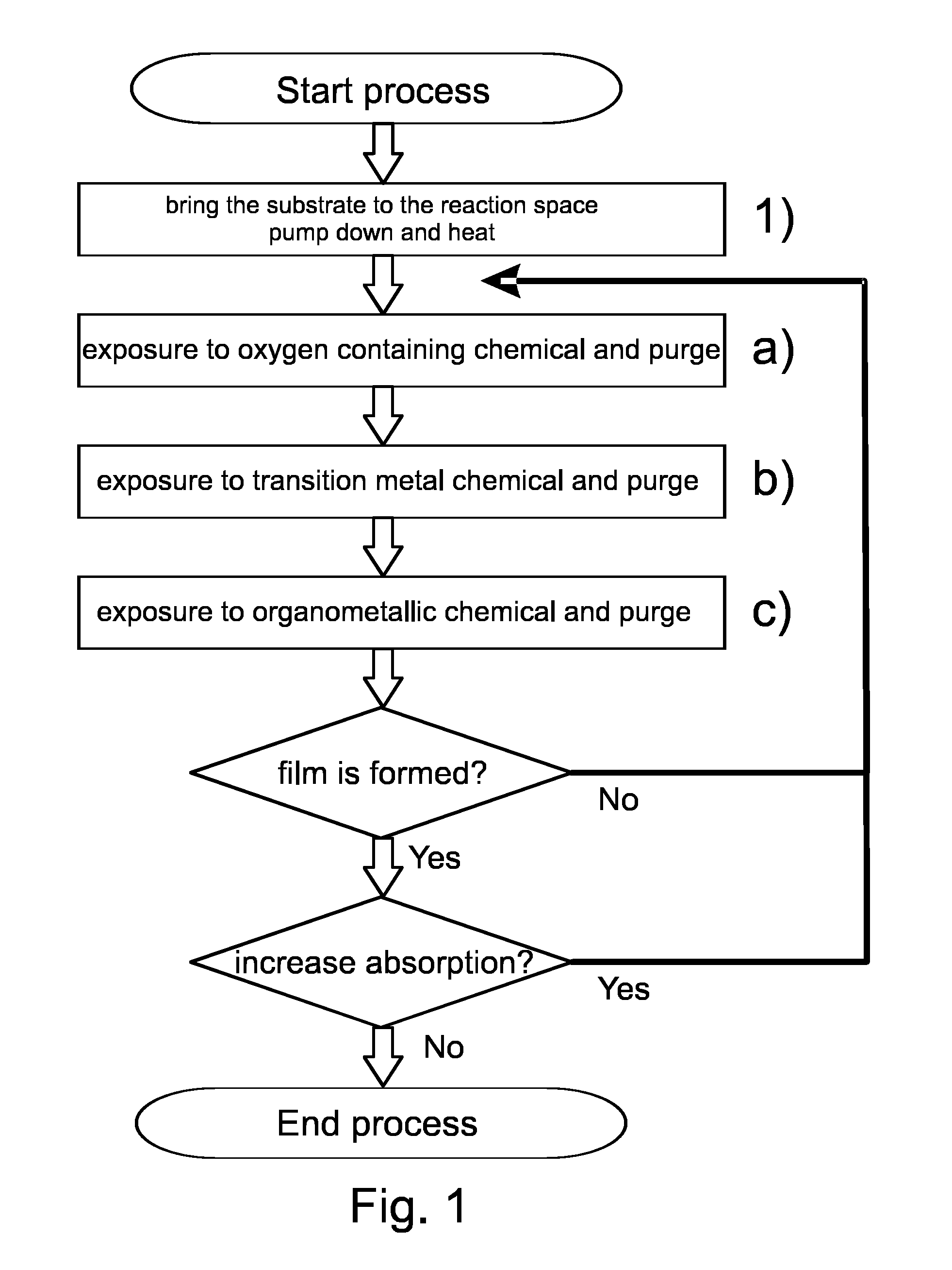
[0075]Using different processing temperatures absorbing films were formed on substrates according to the first embodiment of the invention (see FIG. 1). Visibly essentially transparent D263T glass substrates with a thickness of 0.3 mm (available from Schott AG, Germany) were first inserted inside the reaction space of a P400 ALD batch tool (available from Beneq OY, Finland). The substrates were planar to enable reliable optical transmission measurements. The substrates were positioned inside the reaction space such that both sides of the substrate glass were exposed (i.e. not masked) to the surrounding reaction space. In this example the carrier gas discussed above, and responsible for purging the reaction space, was nitrogen (N2).

[0076]After preparations for loading the substrates into the ALD tool, the reaction space of the ALD tool was pumped down to underpressure and a continuous flow of carrier gas was set to achieve the processing pressure of about 1 mbar (1 hPa) and the subst...

example 2

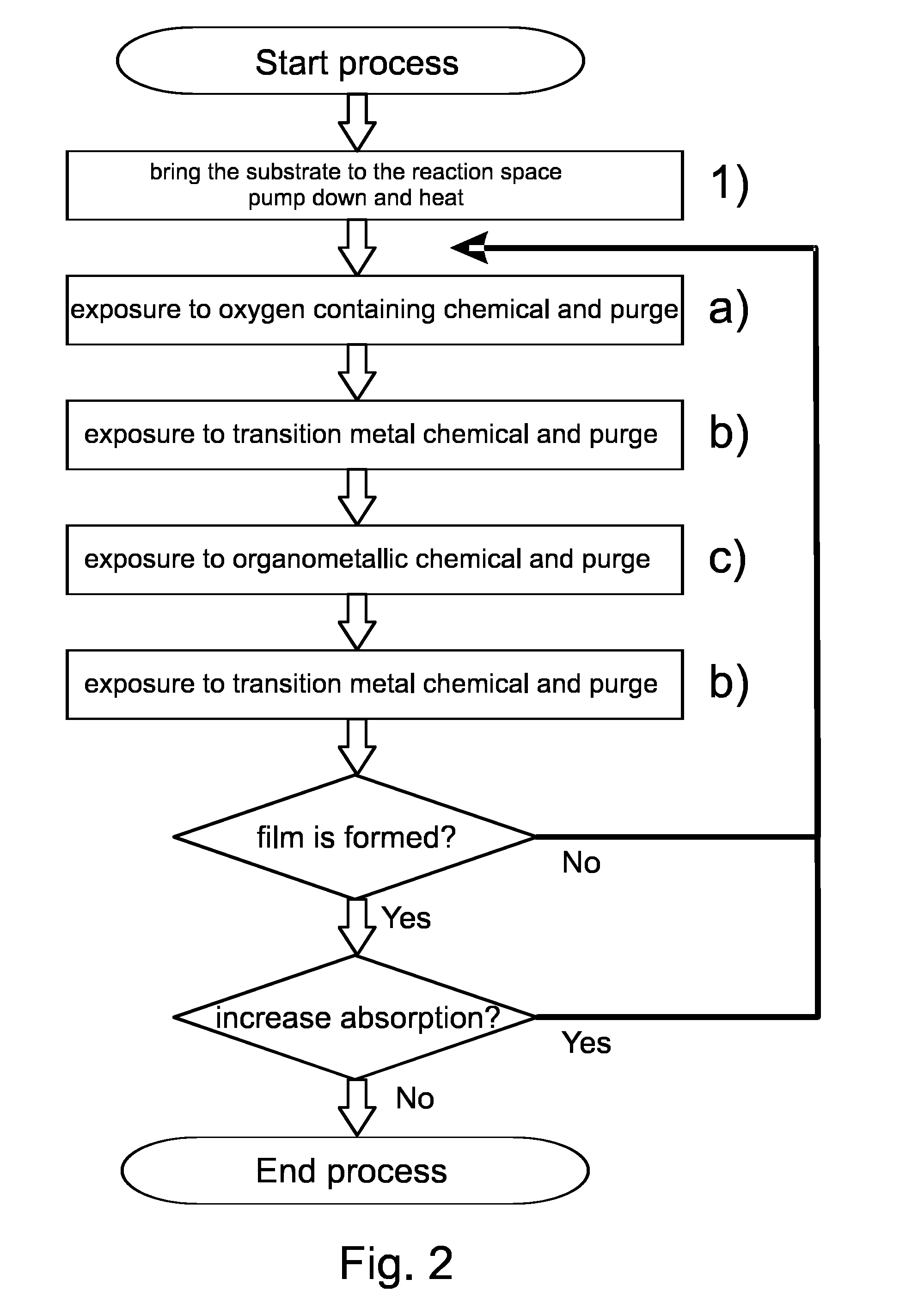
[0083]Absorbing films were formed on substrates according to the second embodiment of the invention (see FIG. 2). Visibly essentially transparent D263T glass substrates with a thickness of 0.3 mm (available from Schott AG, Germany) were first inserted inside the reaction space of a P400 ALD batch tool (available from Beneq OY, Finland). The substrates were planar to enable reliable optical transmission measurements. The substrates were positioned inside the reaction space such that both sides of the substrate glass were exposed (i.e. not masked) to the surrounding reaction space. In this example the carrier gas discussed above, and responsible for purging the reaction space, was nitrogen (N2).

[0084]After preparations for loading the substrates into the ALD tool, the reaction space of the ALD tool was pumped down to underpressure and a continuous flow of carrier gas was set to achieve the processing pressure of about 1 mbar (1 hPa) and the substrates were subsequently heated to the p...


PUM

PropertyMeasurementUnit
Temperatureaaaaaaaaaa

Abstract

A decorative coating and a method for forming a decorative coating on a substrate (2). The decorative coating comprises an absorbing film (1) to attenuate the transmission of visible light through the coating. The method comprises the steps of bringing the substrate (2) into a reaction space, and depositing the absorbing film (1) on the substrate (2). Depositing the absorbing film (1) on the substrate comprises the steps of forming a preliminary deposit of transition metal oxide on the deposition surface and subsequently purging the reaction space, and treating the deposition surface with an organometallic chemical comprising first metal and subsequently purging the reaction space. The steps of forming the preliminary deposit and treating the deposition surface are alternately repeated to increase absorption of the absorbing film (1).

Description

FIELD OF THE INVENTION[0001]The present invention relates to decorative coatings. Especially the present invention relates to a decorative coating and a method for forming a decorative coating comprising an absorbing film deposited by forming a deposit on a substrate and treating this deposit with a chemical. The invention also relates to uses of this method and of the decorative coating.BACKGROUND OF THE INVENTION[0002]Decorative coatings are commonly employed on objects to modify their appearance. The surface of an object can be e.g. painted or metalized to change the color of the object. A dielectric thin-film structure can also be deposited on the surface of an object to impart a special appearance to the object by the reflectance spectrum of the structure which is a result of interference of light in the thin-film structure.[0003]Optical interference structures, or thin-film filters or dichroic filters as they are often called, commonly employ transparent thin-films with differ...

Claims


Application Information

Patent Timeline
IPC IPC(8): G02B5/28G02B5/22C23C16/40C23C16/44B32B33/00C23C16/18
CPCC23C16/08C23C16/18C23C16/40C23C16/403C23C30/00C23C16/4408C23C16/45523C23C28/00C23C16/405
Inventor MAULA, JARMOALASAARELA, TAPANI
Owner BENEQ OY
Why Eureka
Try Eureka