
Simultaneous tx-rx for MRI systems and other antenna devices

a technology of mri and mri-rx, which is applied in the direction of reradiation, measurement using nmr, instruments, etc., can solve the problems of overloaded or damaged preamps, extremely small rf signal of interest, and propose a means of electrically activating switches, etc., to achieve better identification and/or removal, and efficient and flexible

Active Publication Date: 2012-09-06
LIFE SERVICES
View PDF3 Cites 80 Cited by
  • Summary
  • Abstract
  • Description
  • Claims
  • Application Information

AI Technical Summary

Benefits of technology

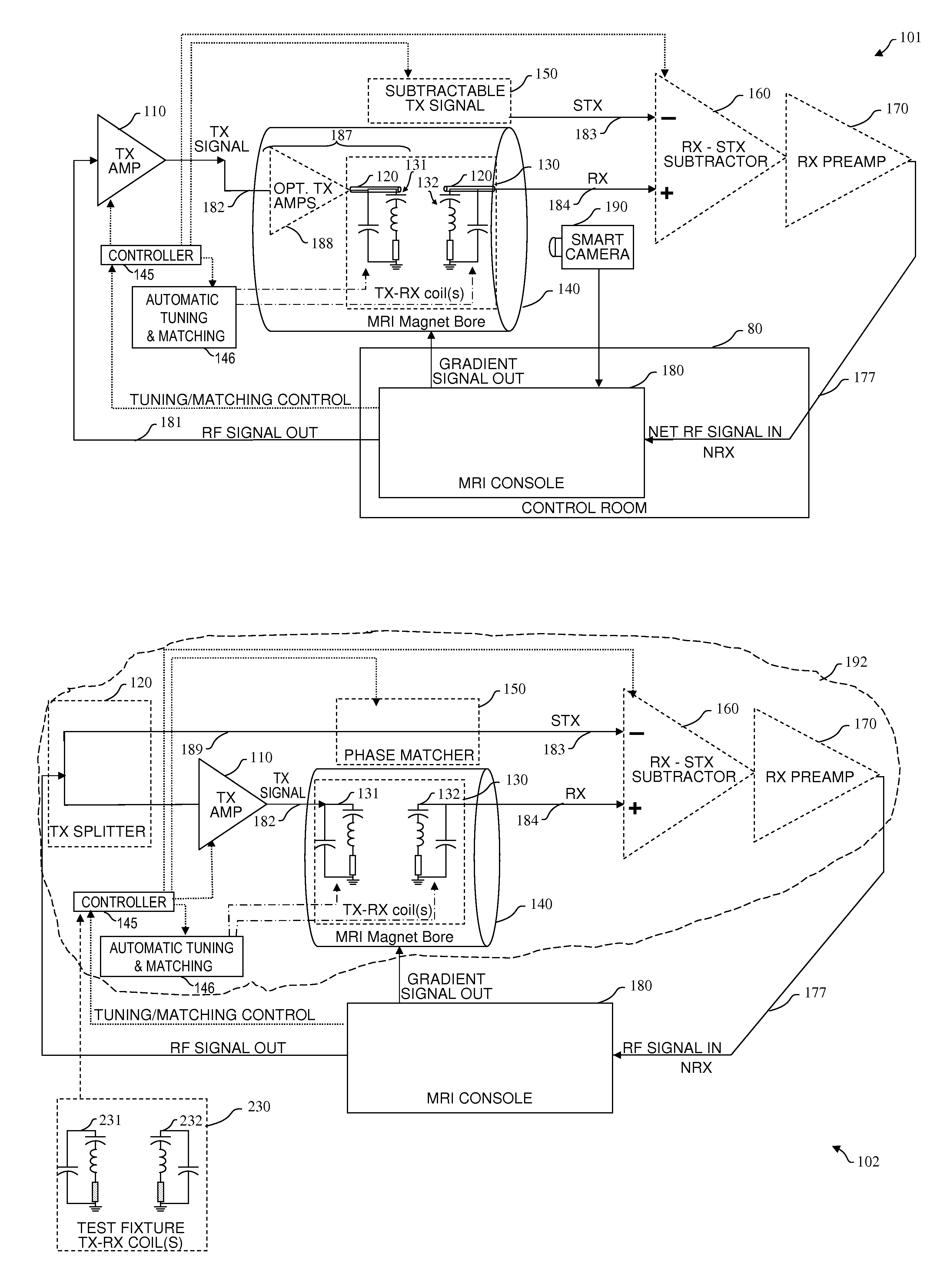
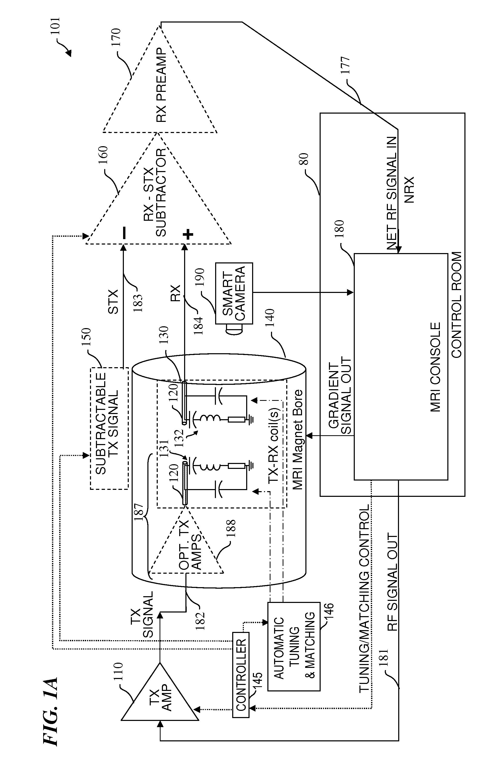
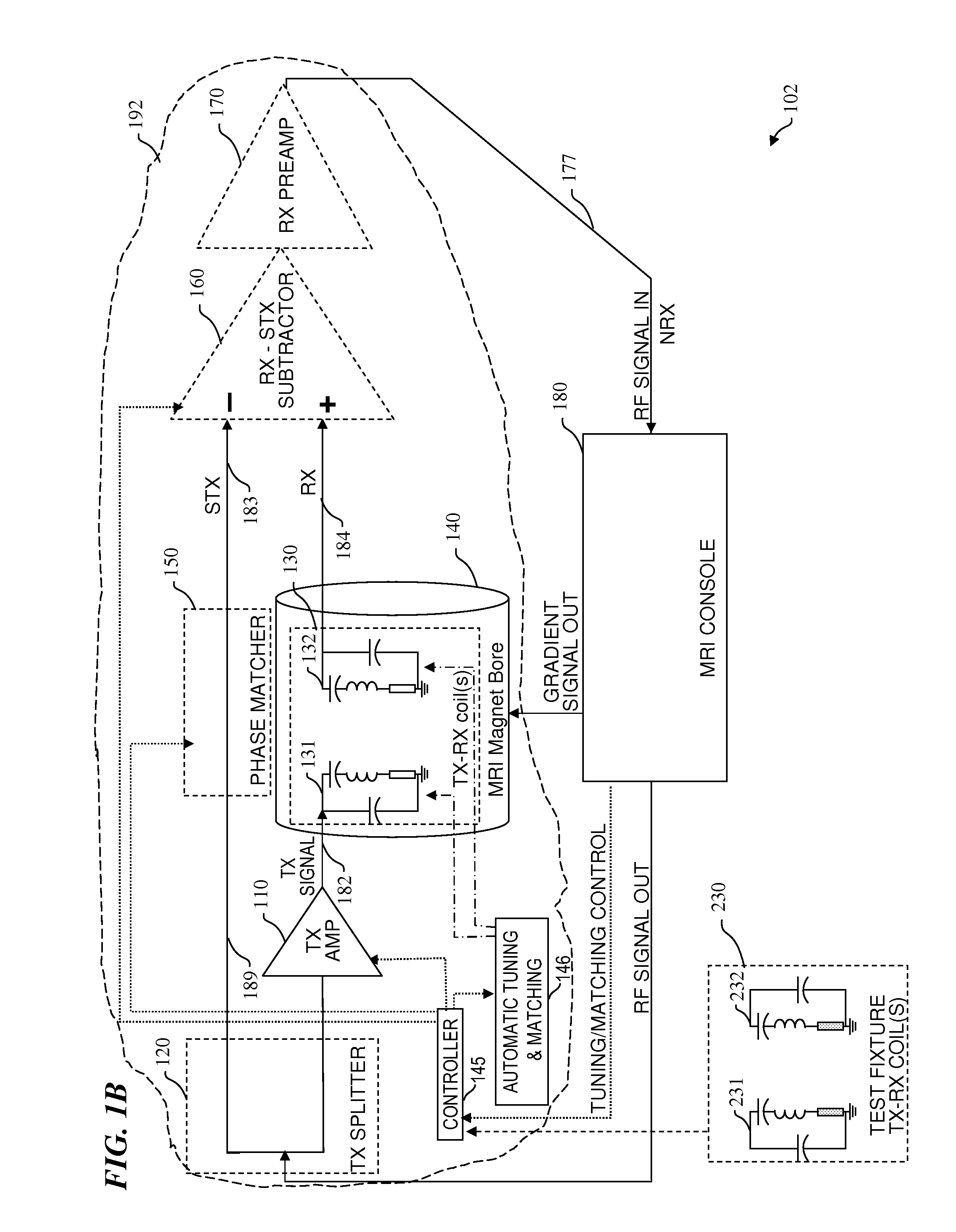
[0045]The present invention provides a more efficient and flexible way to obtain and connect high-power RF transmit signals (TX) to RF-coil devices in an MR machine and simultaneously receive signals (RX) and separate net receive signals NRX) of interest by subtracting a subtractable version of the transmit signal (STX) from the RX and preamplifying the NRX and signal processing the preamplified NRX. In some embodiments, the signal processing includes further removing artifacts of the transmitted signal, e.g., by digitizing the NRX signal, storing the digitized NRX signal in a memory, and performing digital signal processing. In some embodiments, the present invention also includes pre-distorting the TX signals in order to be better able to identify and / or remove the remaining artifacts of the transmitted signal from the NRX signal. This solution also applies to other high-power RF-transmit-antennae signals.
[0046]In some embodiments, the present invention includes combinations that also include the apparatus and methods described in copending U.S. patent application Ser. No. 12 / 879,000 titled “ACTIVE TRANSMIT ELEMENTS FOR MRI COILS AND OTHER ANTENNA DEVICES” filed 9 Sep. 2010 by John Thomas Vaughan, Jr. et al. (Attorney Docket Number: 5268.002US1), which is incorporated herein by reference. These combinations provide the following additional advantages that are further enhanced by simultaneous transmit-receive:
[0047]fewer and lower-power power amplifiers can be used because the losses in the combiner and coaxial cable (frequently called just “coax”) are avoided (this also reduces cost and reduces failure rates by eliminating the combiners and coaxial cabling),
[0050]there is more room around the patient, reducing the claustrophobic feeling that otherwise results from the massive cabling otherwise needed, and
[0051]locating the power amplifiers and / or the transmit / receive (T / R) switches in the coil enclosure provides increased flexibility in circuit layout and coil-element positioning, and allows additional functionality (such as automatic tuning and impedance matching) to be provided for the transmit circuitry and the T / R switching circuitry.
[0054]In some embodiments, the circuitry incorporated in the RF coil in the magnet bore further includes the RF oscillators needed for the transmit signals (TX and STX), and thus only control signals need be sent from the control room to the RF coil in the magnet bore, further reducing bandwidth requirements, and facilitating even wireless control of the RF transmit signals. In some embodiments, wireless transmission is also used for the signals received by and processed in the RF-coil device (i.e., wirelessly transmitting the NRX), and thus the only wiring needed in some embodiments is electrical-power cabling (e.g., in some embodiments, cabling for DC voltage and current) that is used to supply electrical power to the power amplifiers of the transmit stages, the T / R switches, and the pre-amplifiers of the receive stages.

Problems solved by technology

Because of the high power of the RF transmit signal, it is infeasible to wirelessly couple it from the remote control-room power amplifiers to the RF-coil device in the MR magnet bore.
The received RF signal of interest is extremely small compared to the transmit signal, and the receive pre-amplifiers (preamps) would be overloaded or damaged if they are coupled to the receive antenna at a time simultaneous with the excitation RF pulse being transmitted.
They did not propose a means for electrically activating such switches.

Method used


Image

  • Simultaneous tx-rx for MRI systems and other antenna devices
  • Simultaneous tx-rx for MRI systems and other antenna devices
  • Simultaneous tx-rx for MRI systems and other antenna devices

Examples


Embodiment Construction

[0080]Although the following detailed description contains many specifics for the purpose of illustration, a person of ordinary skill in the art will appreciate that many variations and alterations to the following details are within the scope of the invention. Accordingly, the following preferred embodiments of the invention are set forth without any loss of generality to, and without imposing limitations upon the claimed invention. Further, in the following detailed description of the preferred embodiments, reference is made to the accompanying drawings that form a part hereof, and in which are shown by way of illustration specific embodiments in which the invention may be practiced. It is understood that other embodiments may be utilized and structural changes may be made without departing from the scope of the present invention.

[0081]The leading digit(s) of reference numbers appearing in the Figures generally corresponds to the Figure number in which that component is first intr...


PUM


Abstract

Apparatus and method that are more efficient and flexible, and obtain and connect high-power RF transmit signals (TX) to RF-coil devices in an MR machine or other devices and simultaneously receive signals (RX) and separate net receive signals NRX) of interest by subtracting or filtering to remove the subtractable portion of the transmit signal (STX) from the RX and preamplifying the NRX and signal processing the preamplified NRX. In some embodiments, signal processing further removes artifacts of the transmitted signal, e.g., by digitizing the NRX signal, storing the digitized NRX signal in a memory, and performing digital signal processing. In some embodiments, the present invention also includes pre-distorting the TX signals in order to be better able to identify and / or remove the remaining artifacts of the transmitted signal from the NRX signal. This solution also applies to other high-power RF-transmit-antennae signals.

Description

CROSS-REFERENCE TO RELATED APPLICATIONS[0001]This invention claims priority benefit under 35 U.S.C. §119(e) of U.S. Provisional Patent Application No. 61 / 447,673 filed Feb. 28, 2011 by Scott M. Schillak et al., titled “SIMULTANEOUS TX-RX FOR MRI SYSTEMS AND OTHER ANTENNA DEVICES” (Attorney Docket 5268.009PV1), which is incorporated herein by reference in its entirety.FIELD OF THE INVENTION[0002]This invention relates to the field of transceiver antenna circuits, and more specifically to a method and apparatus for receiving an RF (radio frequency) signal while simultaneously transmitting a signal of like frequency into a common volume of space, wherein the received signal is processed to remove the unwanted received portion of the transmitted signal to leave the desired receive signal of interest. The present invention is applicable to magnetic-resonance imaging and spectroscopy where the transmitted excitation signal needs to be removed from the received signal to obtain the MR resp...

Claims


Application Information

Patent Timeline
IPC IPC(8): G01R33/48
CPCG01R33/3415G01R33/3607G01R33/3621G01R33/3692G01R33/3614G01R33/54
Inventor SCHILLAK, SCOTT M.VAUGHAN, JR., JOHN THOMASLEMAIRE, CHARLES A.WAKS, MATTHEW T.
Owner LIFE SERVICES
Learn More