Transceiver, voltage control oscillator thereof and control method thereof

Active Publication Date: 2012-09-06
REALTEK SEMICON CORP
View PDF8 Cites 3 Cited by
  • Summary
  • Abstract
  • Description
  • Claims
  • Application Information

AI Technical Summary

Benefits of technology

[0006]One object of the invention is to provide a vol...

Problems solved by technology

However, the designed smaller KVCO may result in difficulty of covering larger temperature or voltage...

Method used


Image

  • Transceiver, voltage control oscillator thereof and control method thereof
  • Transceiver, voltage control oscillator thereof and control method thereof
  • Transceiver, voltage control oscillator thereof and control method thereof

Examples


Embodiment Construction

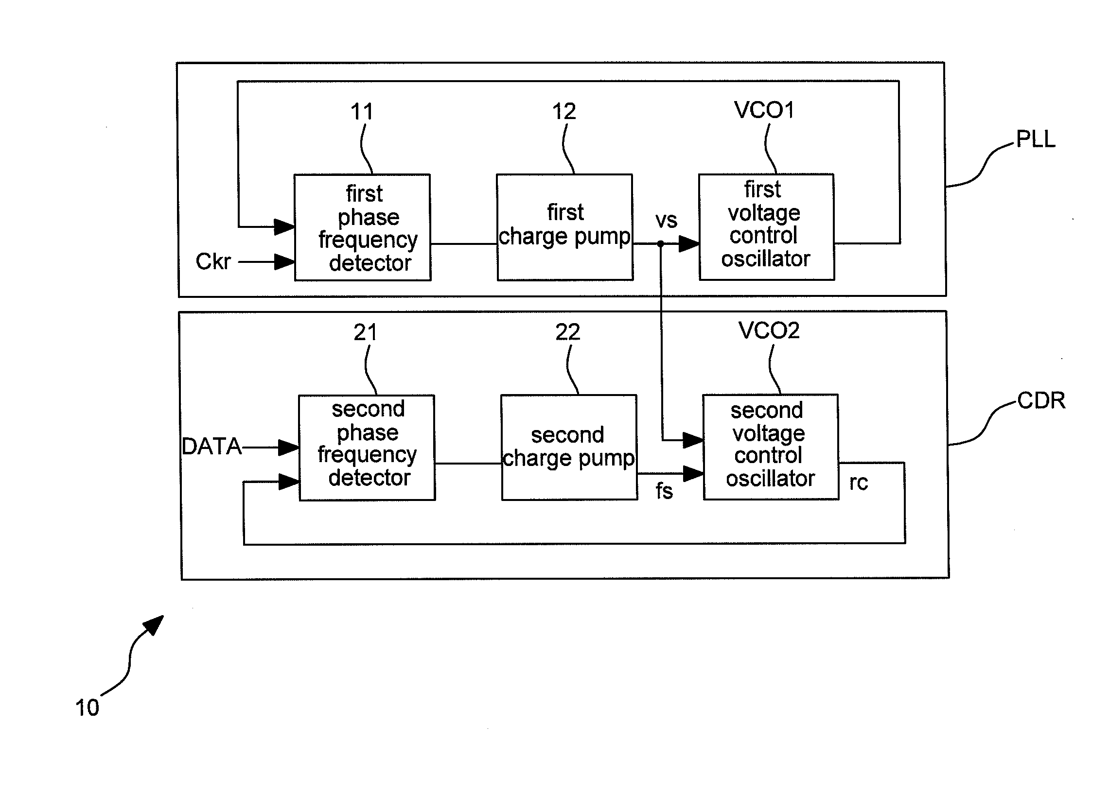
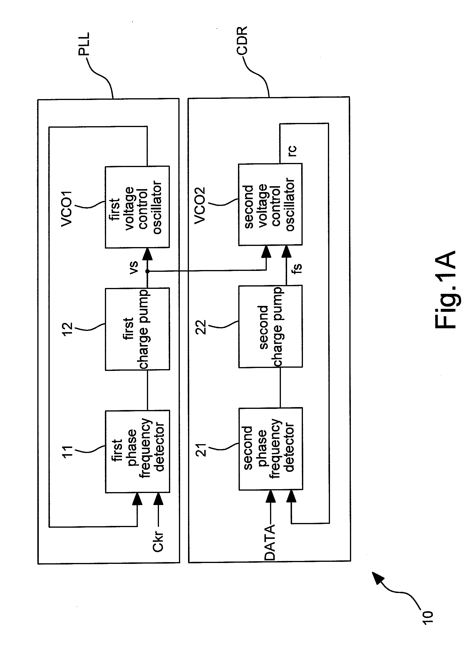
[0022]FIG. 1A shows a schematic diagram illustrating a transceiver according to an embodiment of the invention. The transceiver 10 includes a phase lock loop PLL and a clock data recovery circuit CDR.

[0023]The phase lock loop PLL includes a first phase frequency detector 11, a first charge pump 12 and a first voltage control oscillator VCO1. In an embodiment, a clock Ckr as shown in FIG. 1A is generated by a stable clock generator.

[0024]The clock data recovery circuit CDR couples to the phase lock loop PLL. The clock data recovery circuit CDR includes a second phase frequency detector 21, a second charge pump 22 and a second voltage control oscillator VCO2. In an embodiment, the phase lock loop PLL and the clock data recovery circuit CDR may further include a loop filter to filter noises of signals.

[0025]The clock data recovery circuit CDR of an embodiment locks a received data signal DATA according to a second level control signal fs generated by the second charge pump 22 so as to ...


PUM


Abstract

A transceiver includes a phase lock loop (PLL) and a clock data recovery circuit (CDR). The phase lock loop generates a first level control signal. The clock data recovery circuit, coupled to the phase lock loop, locks an incoming data signal to generate a data recovery clock according to a second level control signal. Wherein the clock data recovery circuit receives the first level control signal to further control a frequency range of the data recovery clock.

Description

BACKGROUND OF THE INVENTION[0001](a) Field of the Invention[0002]The invention relates to a device, particularly to a voltage control oscillator and control method thereof.[0003](b) Description of the Related Art[0004]Applications, like PCIE (Peripheral Component Interconnection EXPRESS), universal serial bus (such as USB 3.0), etc., may use a transceiver to receive or transmit data. The transceiver usually comprises various circuit modules, such as a phase lock loop (PLL), a clock data recovery (CDR) circuit, etc.[0005]Further a clock data recovery (CDR) circuit usually includes a voltage control oscillator (VCO). In the system design, the voltage control oscillator needs to have a broader frequency range and a smaller KVCO so that the clock data recovery circuit can lock frequency in a broader frequency range and output a signal with lowered jitter. However, the designed smaller KVCO may result in difficulty of covering larger temperature or voltage variation after the clock data ...

Claims


Application Information

Patent Timeline
IPC IPC(8): H03L7/08
CPCH03L7/0807H03L7/07H03L7/0805H03L7/0995
Inventor ZHAO, HAIBING
Owner REALTEK SEMICON CORP
Why Eureka
Try Eureka