
Setting a Reference Voltage in a Memory Controller Trained to a Memory Device

a memory controller and reference voltage technology, applied in the field of training impedance values, can solve the problems of reducing the width of the data eye, or timing margin, compromising data accuracy, etc., and achieve the effects of reducing signal errors, improving timing margins, and reducing impedance mismatches

Inactive Publication Date: 2012-09-06
INT BUSINESS MASCH CORP
View PDF6 Cites 2 Cited by
  • Summary
  • Abstract
  • Description
  • Claims
  • Application Information

AI Technical Summary

Benefits of technology

This approach reduces signal errors, increases communication speed, and enhances timing margins by adjusting the reference voltage based on real-time data comparisons, effectively managing impedance mismatches between memory devices and controllers.

Problems solved by technology

Mismatching impedances of the memory device and the memory controller may reduce a width of the data eye, or timing margin, and compromise data accuracy.

Method used


Image

  • Setting a Reference Voltage in a Memory Controller Trained to a Memory Device
  • Setting a Reference Voltage in a Memory Controller Trained to a Memory Device
  • Setting a Reference Voltage in a Memory Controller Trained to a Memory Device

Examples


Embodiment Construction

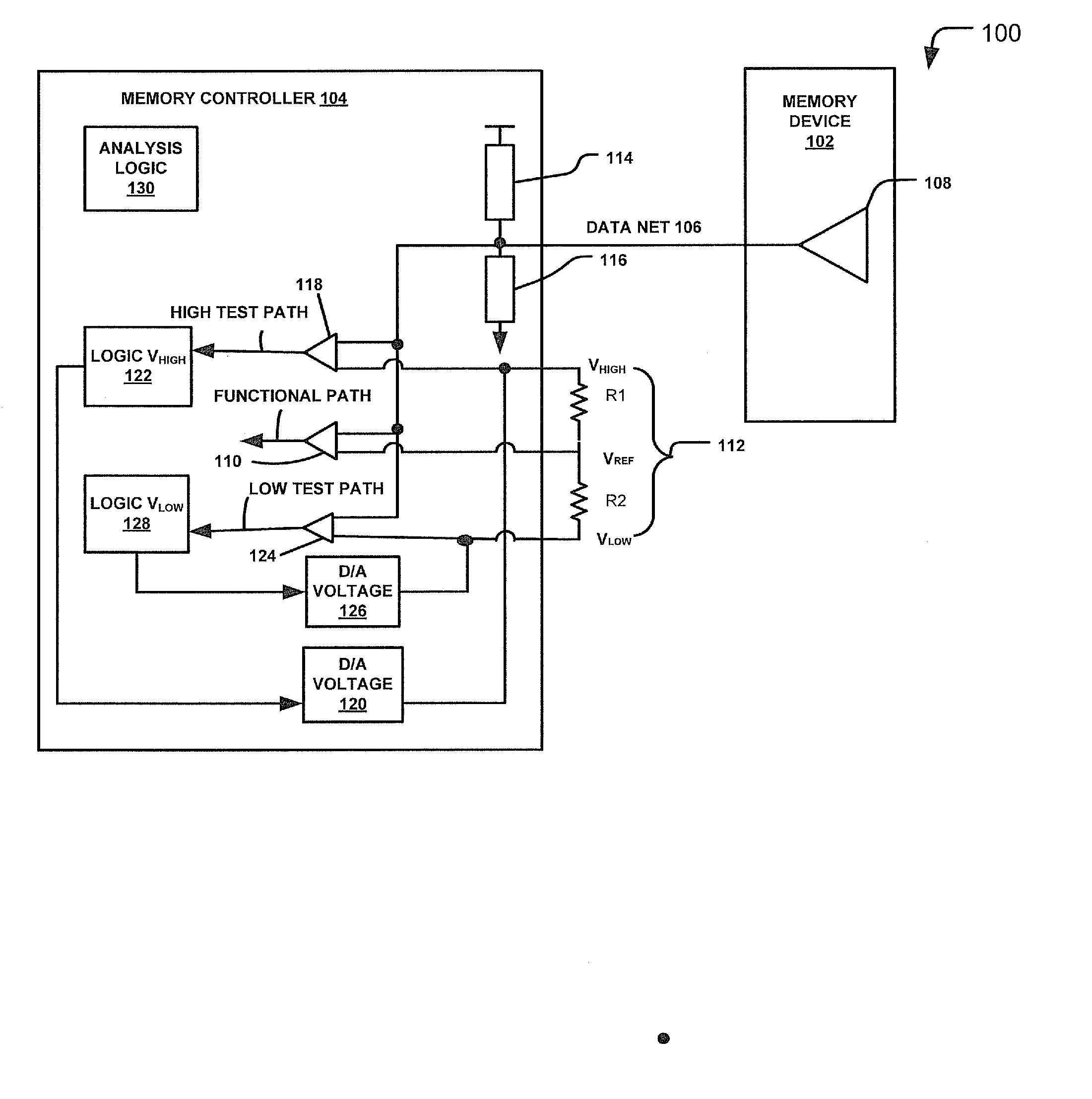
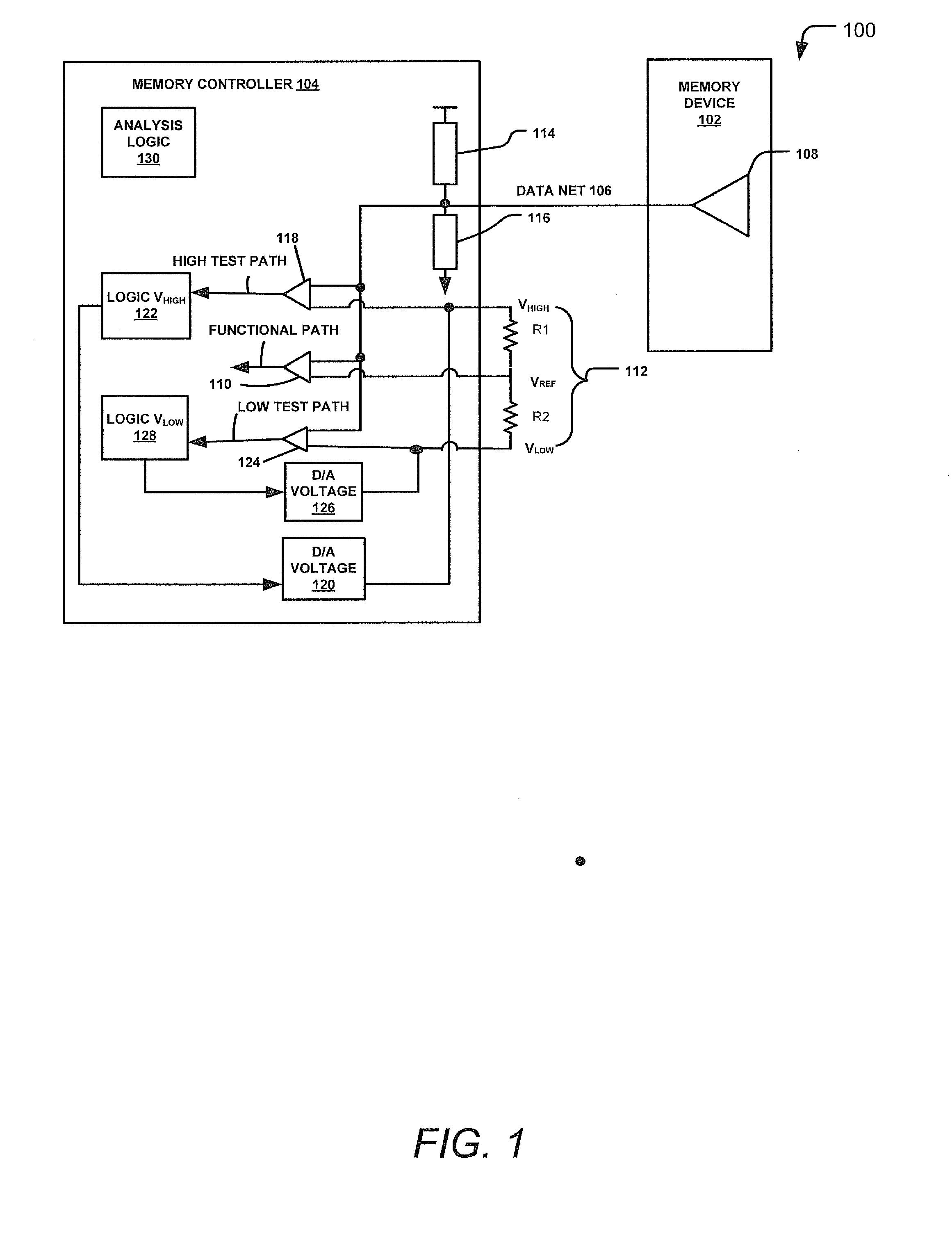
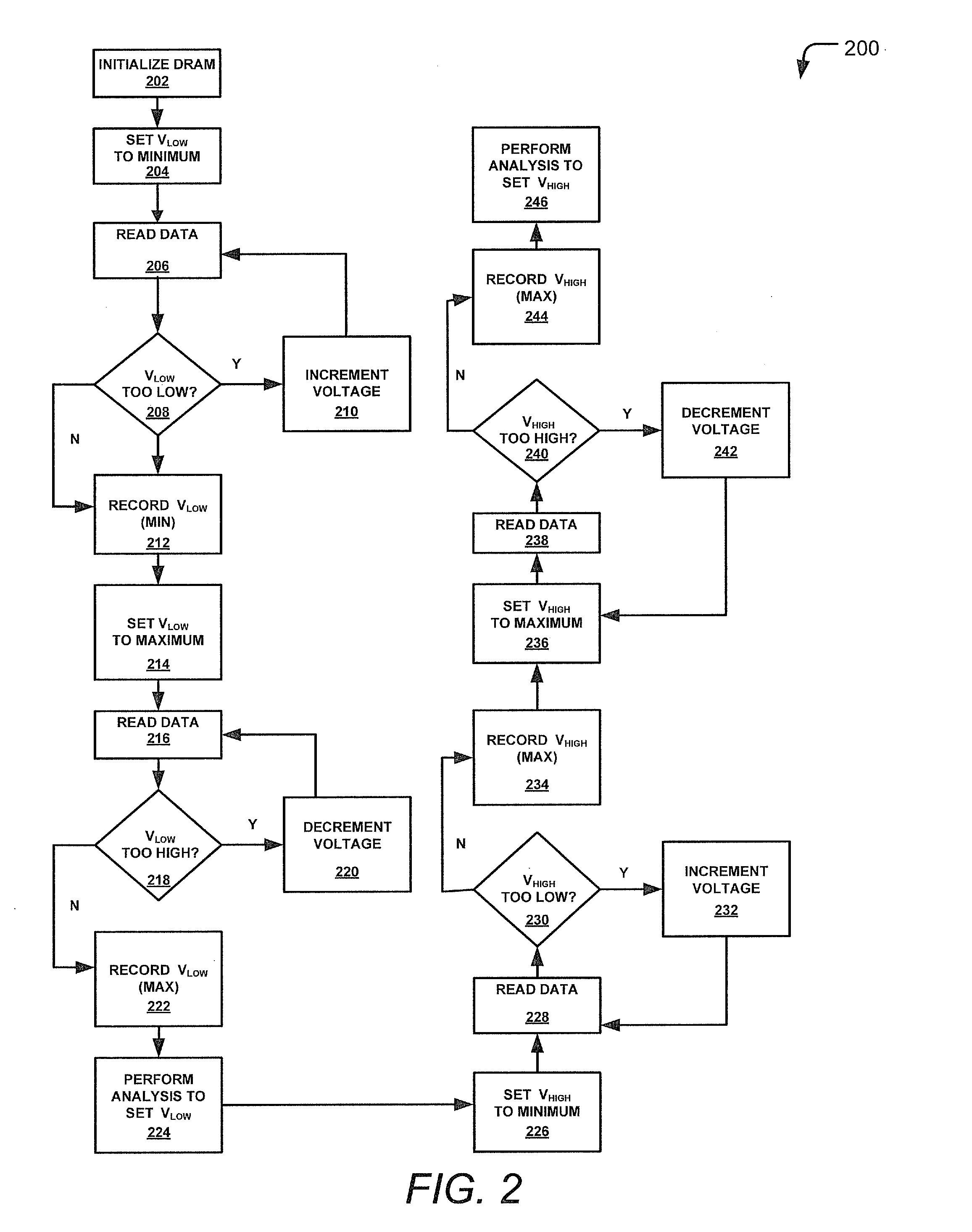
[0014]A memory device and a memory controller linked via a data net may be trained using voltage value adjustment. A reference voltage of the memory controller may be set based on a driver impedance of the memory device and a termination impedance of the memory controller. A voltage may be applied to a resistor arrangement that includes a pair of unmatched (non-identical) resistors. The reference voltage may be set based on a high voltage value and a low voltage value. The high and low voltage values may be automatically updated as one or more test paths are monitored during operation.

[0015]The memory controller may increment or decrement voltages applied to the resistor arrangement to set the high and low voltage values. For example, the correctness of test path data may be determined based on data of a functional path. A percentage of time that correct data (or incorrect data) is read in the test data path may be determined by comparing the test data with the actual data, or funct...


PUM


Abstract

Systems and methods to set a voltage value associated with a memory controller coupled to a memory device are disclosed. A particular method includes comparing test data of a test path to functional data of a functional path. The functional data may be generated based on device data received at a memory controller from a memory device. The test data may be affected by a voltage value applied to a resistor arrangement in electronic communication with the test path. The voltage value may be applied to the resistor arrangement based on the comparison.

Description

I. CLAIM OF PRIORITY[0001]This application is a continuation patent application of, and claims priority from, U.S. patent application Ser. No. 12 / 815,739, filed on Jun. 15, 2010 and entitled “Setting a Reference Voltage in a Memory Controller Trained to a Memory Device” which is incorporated by reference herein in its entirety for all purposes.II. FIELD OF THE DISCLOSURE[0002]The present disclosure relates to training impedance values associated with a memory device coupled to a memory controller.III. BACKGROUND[0003]In a memory bus, the impedances of a memory device and a memory controller can be trained against each other. The training may enable the memory bus to detect a data eye of a signal, such as a signal communicated over a link coupling the memory device to the memory controller. The data eye may include a point on the signal that (when located and sampled) may be used to identify an associated bit as being either a logical one or a zero. Training may include adjusting an ...

Claims


Application Information

Patent Timeline
Patent Type & Authority Applications(United States)
IPC IPC(8): G11C7/00
CPCG11C29/02G11C29/022G11C29/025Y02B60/1285G11C29/50008G06F1/3296G11C29/028Y02D10/00
Inventor FOX, BENJAMIN A.HOVIS, WILLIAM P.LIANG, THOMAS W.RUDRUD, PAUL W.
Owner INT BUSINESS MASCH CORP
Learn More