Fault Localization and Fiber Security in Optical Transponders

a technology of optical transponders and fiber security, applied in the field of optical transmission systems, can solve the problems of multiple otdrs at additional real-estate, power, maintenance and cost, and inability to easily identify the exact location of the fault,

Active Publication Date: 2012-09-06
ACACIA CHEM
View PDF24 Cites 64 Cited by
  • Summary
  • Abstract
  • Description
  • Claims
  • Application Information

AI Technical Summary

Benefits of technology

[0015]Another aspect of this invention relates to using coherent transponders such as DP-QPSK, DP-QAM, or OFDM transponders that have sophisticated digital signal processing (DSP) to correct for fiber impairments such as polarization rotation, polarization mode dispersion, and chromatic dispersion. Such DSP algorithms inherently correct for these continually varying fiber characteristics. By modifying the DSP algorithms to report these parameters to a processing unit, and the processing unit in combination with the previously mentioned time synchronization algorithms can predict, detect and precisely locate the nature and position of natural or man-made problems that are innocent or malicious in their intent, in near real-time or post-processing non-real-time.

Problems solved by technology

While the fault itself can be detected quickly, its location cannot be easily identified precisely (e.g., not better than a typical amplifier-to-amplifier distance of about 100 km) unless expensive equipment such as an OTDR is dedicated to each link.
Furthermore, if there are multiple transmission fiber pairs between each link then multiple OTDRs may be required at additional real-estate, power, maintenance and cost.
Fiber cuts result in abrupt traffic outage and is therefore immediately noticeable and can be located within an amplifier but distance with simple techniques using network management protocols that are usually transmitted over a dedicated communication link that is entirely different (out of fiber) and operated at a different wavelength than the wavelength of the signal channels.
Slowly occurring degradation in transmission quality resulting from impairments that are not easily noticeable such as, an event of malicious tampering of an otherwise secured transmission link by a third party for eaves dropping, are more difficult to detect.
While a back-hoe near a distant amplifier but may cut the fiber and take down all the communication channels in a very noticeable and abrupt way, a malicious determined third party might be much more sinister in its ability to individually select one fiber to tap some of the light for eaves dropping or other malicious intentions such as spoofing or jamming.
They are very difficult and expensive to detect with technology solutions currently available.

Method used


Image

  • Fault Localization and Fiber Security in Optical Transponders
  • Fault Localization and Fiber Security in Optical Transponders
  • Fault Localization and Fiber Security in Optical Transponders

Examples


Embodiment Construction

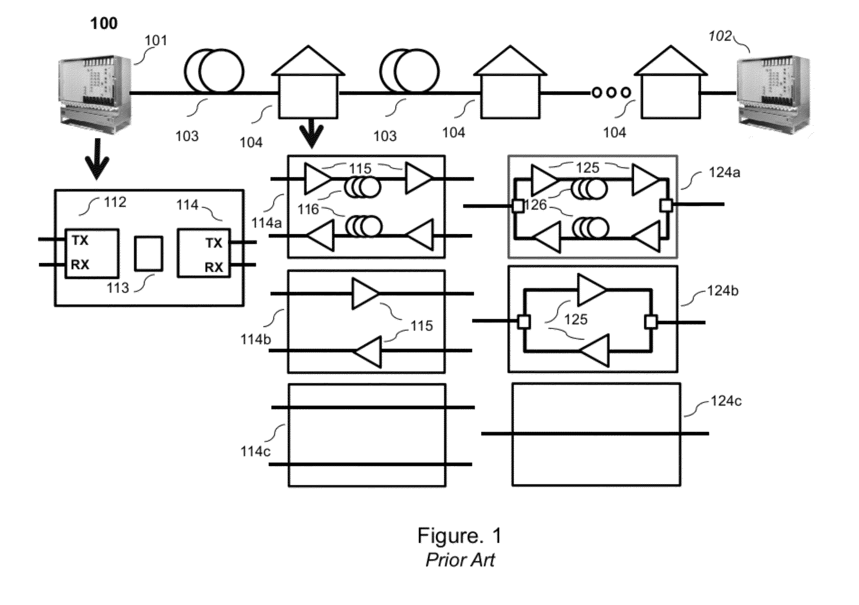
[0024]Referring once again to FIG. 1, it may be envisioned that there are many installation scenarios for example, local, metropolitan, regional, or long-haul links that may be of interest to system vendors and their end customers who are telecommunication companies, cable operators, data centers, government organizations, etc. The DWDM systems may use a variety of types of fiber (standard, dispersion shifted, Truewave™), different types of amplifiers (single stage, multiple stages with or without mid-stage access, Raman-end pumped systems, etc.), and be unidirectional or bidirectional systems as is known in the art.

[0025]This invention can be applied to any transmission link and will be described in few representative embodiments. The preferred embodiments illustrate a general broad framework of the invention, and the methods outlined here may be applied in different combinations, sub-combinations and modifications in commercial and military networks for applications including, but...


PUM


Abstract

Designs, methods, and applications for fault localization and fiber security in optical transponders is described. In one embodiment a two-way time transfer protocol or other suitable method for synchronizing clocks between distant transponders is used. The clock synchronized transponders have digital signal processing to continually detect high precision time-histories of physical layer attributes in the transmission between the two transponders. Physical layer attributes can include: state-of-polarization changes, changes in polarization-mode-dispersion, change in propagation delay, changes or loss-of-light, changes in OSNR, changes in BER between the two nodes. By recording these physical layer changes and time-stamping them information on the magnitude and estimated location of the changes can be inferred by from the time records. In one aspect the method may be used in a distributed optical sensor for monitoring trespassing events that are a risk to fiber security of an optical transmission link.

Description

CROSS REFERENCE TO RELATED APPLICATION[0001]This application claims priority from the U.S. Provisional Patent Application No. 61 / 448,835 filed on Mar. 3, 2011.BACKGROUND OF THE INVENTION[0002]1. Field of the Invention[0003]This invention relates generally to the field of optical transmission systems, and more particularly to optical transceivers used in optical transmission systems that use analog and digital signal process (DSP) and time synchronization techniques to predict, detect, and localize faults or other impairments to an optical fiber transmission link resulting from damage or tampering or a transmission link that is configured as a distributed sensor.[0004]2. Related Art[0005]In optical fiber transmission systems it is important to be able to predict, detect, and locate faults resulting from link damage or tampering along a transmission path. There exists a variety of methods to accomplish these tasks. For example, if a back-hoe accidentally cuts a transmission fiber cond...

Claims


Application Information

Patent Timeline
Patent Type & Authority Applications(United States)
IPC IPC(8): H04B10/08
CPCH04B10/0705H04B10/85H04L41/0631H04L43/0852H04L43/16
Inventor SWANSON, ERIC A.PENDOCK, GRAEME
Owner ACACIA CHEM
Why Eureka
Try Eureka