Deep leach pressure vessel for shear cutters

Active Publication Date: 2012-09-13
SMITH INT INC
View PDF7 Cites 19 Cited by
  • Summary
  • Abstract
  • Description
  • Claims
  • Application Information

AI Technical Summary

Benefits of technology

[0015]In one aspect, embodiments disclosed herein relate to a system for producing thermally stable cutting elements including a heat source, a pressure vessel, at least one polycrystalline diamond body attached to a carbide substrate, and a leaching agent, wherein the heat source includes a container comprising at least one receiving mechanism and at least one retention mechanism, and wherein the carbide substrate is disposed in the at least one receiving mechanism of the pressure vessel, and wherein the polycrystalline diamond body comprises interconnected diamond particles with a catalyzing

Problems solved by technology

This heat causes thermal damage to the PCD in the form of cracks (due to differences in thermal expansion coefficients), which lead to spalling of the PCD body or layer, and/or delamination between the PCD body and substrate, and/or back conversion of the diamond to graphite in the PCD body causing rapid abrasive wear.
Conventional PCD is stable at temperatures of up to about 700 to 750° C., after which observed increases in temperature may result in permanent damage to and structural failure of PCD.
This deterioration in PCD is due to the significant difference in the coefficient of thermal expansion of the binder or catalyst material, for example, as compared to diamond.
Upon heating of PCD during use, the catalyst material and the diamond lattice expands at different rates, which may cause cracks to form in the diamond lattice structure and result in deterioration of the PCD.
Damage is also due to the catalyzed formation of graphite at diamond-diamond ne

Method used


Image

  • Deep leach pressure vessel for shear cutters
  • Deep leach pressure vessel for shear cutters
  • Deep leach pressure vessel for shear cutters

Examples


examples

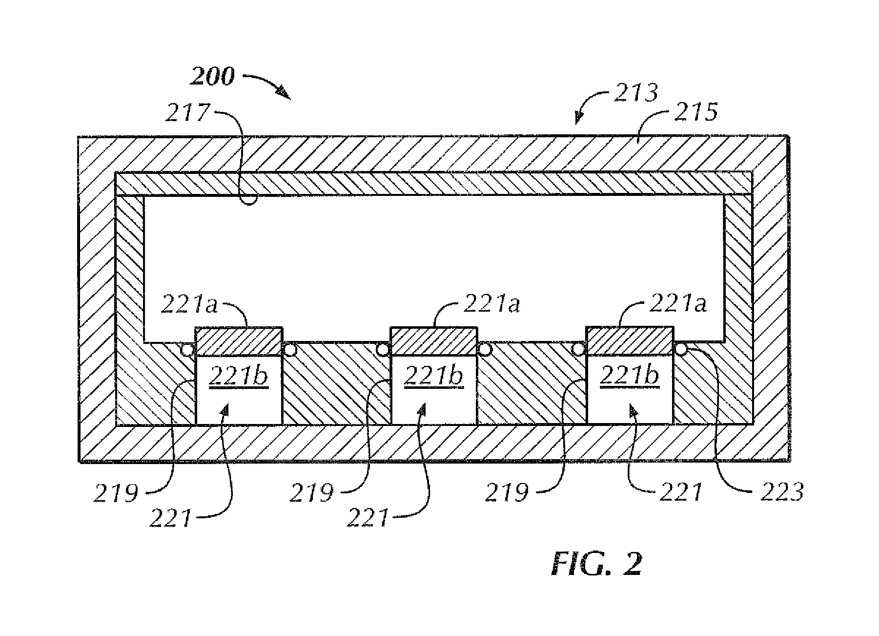
[0047]In accordance with one embodiment of the present disclosure, a plurality of carbide substrates having PDC bodies attached thereto are press fit into cups formed in the liner of a pressure vessel which contains a selected amount of leaching agent, wherein at least a portion of the PDC bodies protrude out from the cups and are exposed to the leaching agent, and wherein retention mechanisms, for example, TEFLON coated o-rings, are used to retain the carbide substrates within the cups and protect the carbide substrates from being exposed to the leaching agent. The exposed PDC bodies remain exposed for a selected time to elevated temperatures, for example 160° C., and experience elevated pressure levels, for example, 500 psi (or around 34 bar).

[0048]Those having ordinary skill in the art will appreciate that in other embodiments the temperature and pressure levels may be adjusted to control the overall leaching depth and time. It should also be appreciated that other factors may be...


PUM

PropertyMeasurementUnit
Temperatureaaaaaaaaaa
Pressureaaaaaaaaaa

Abstract

A system for producing thermally stable cutting elements may include a heat source, a pressure vessel, at least one polycrystalline diamond body attached to a carbide substrate, and a leaching agent is disclosed, wherein the heat source includes a container comprising at least one receiving mechanism and at least one retention mechanism, and wherein the carbide substrate is disposed in the at least one receiving mechanism of the pressure vessel, and wherein the leaching agent is disposed in the pressure vessel, and wherein the leaching agent removes the catalyzing material from the interstitial spaces interposed between the diamond particles of the at least one polycrystalline diamond body, and wherein the at least one retention mechanism of the pressure vessel seals at least a portion of the carbide substrate into the at least one receiving mechanism and prevents the leaching agent from contacting at least a portion of the carbide substrate.

Description

CROSS-REFERENCE TO RELATED APPLICATIONS[0001]This application claims priority to U.S. Patent Application No. 61 / 449,204, filed on Mar. 4, 2012, which is herein incorporated by reference in its entirety.BACKGROUND[0002]1. Technical Field[0003]Embodiments disclosed herein relate generally to systems and methods for producing polycrystalline diamond composites and cutting structures that have high thermal stability. More particularly, embodiments disclosed herein relate to a pressure vessel system capable of removing binder or catalyst material from polycrystalline diamond cutting structures that are attached to a substrate.[0004]2. Background Art[0005]Polycrystalline diamond compact (PDC) cutters have been used in industrial applications including rock drilling and metal machining for many years. In a typical application, a compact of polycrystalline diamond (PCD) (or other superhard material) is bonded to a substrate material, which is typically a sintered metal-carbide to form a cut...

Claims


Application Information

Patent Timeline
IPC IPC(8): B24D18/00B01J19/00
CPCE21B10/567B22F2005/001B22F2998/00C22C2204/00C22C26/00C23F1/02C23F1/08C04B41/5338E21B10/55
Inventor BELNAP, J. DANIELCARIVEAU, PETER THOMASCORBETT, LOELEYRE, RONALD K.
Owner SMITH INT INC
Why Eureka
Try Eureka