Ultra-high vacuum photoelectron linear accelerator

a photoelectron and ultra-high vacuum technology, applied in the direction of linear accelerators, accelerators, electrical devices, etc., can solve the problems of reducing the q-factor of the cavity, limiting the amount of heat that can be removed from the surface of the cavity, and having to replace the entire cavity, etc., to achieve the effect of superior cooling and optimal operation

Inactive Publication Date: 2012-09-13
DULY RES
View PDF6 Cites 5 Cited by
  • Summary
  • Abstract
  • Description
  • Claims
  • Application Information

AI Technical Summary

Benefits of technology

[0006]The present invention provides a method and apparatus to produce a high-quality electron beam from a photocathode which requires an ultra high vacuum for optimal operation, and to provide superior cooling in a half-cell photoelectron linear accelerator under high RF heat load. The invention provides an ultra high vacuum RF photoelectron linear accelerator design that has a perforated cavity wall through which residual gas inside the RF cavity is evacuated with ultra high vacuum pumps placed in a replaceable pressure chamber outside said perforated wall. Examples of UHV pumps are ion pumps, non-evaporative

Problems solved by technology

The presence of the NEG film on the RF cavity wall, however, reduces the Q-factor of the cavity.
As the NEG pumping becomes less effective over time, the entire cavity would have to be replaced.
The flow rates are predominantly limited by the flow area inside the pipes and the sizes of orifi

Method used


Image

  • Ultra-high vacuum photoelectron linear accelerator
  • Ultra-high vacuum photoelectron linear accelerator
  • Ultra-high vacuum photoelectron linear accelerator

Examples


Embodiment Construction

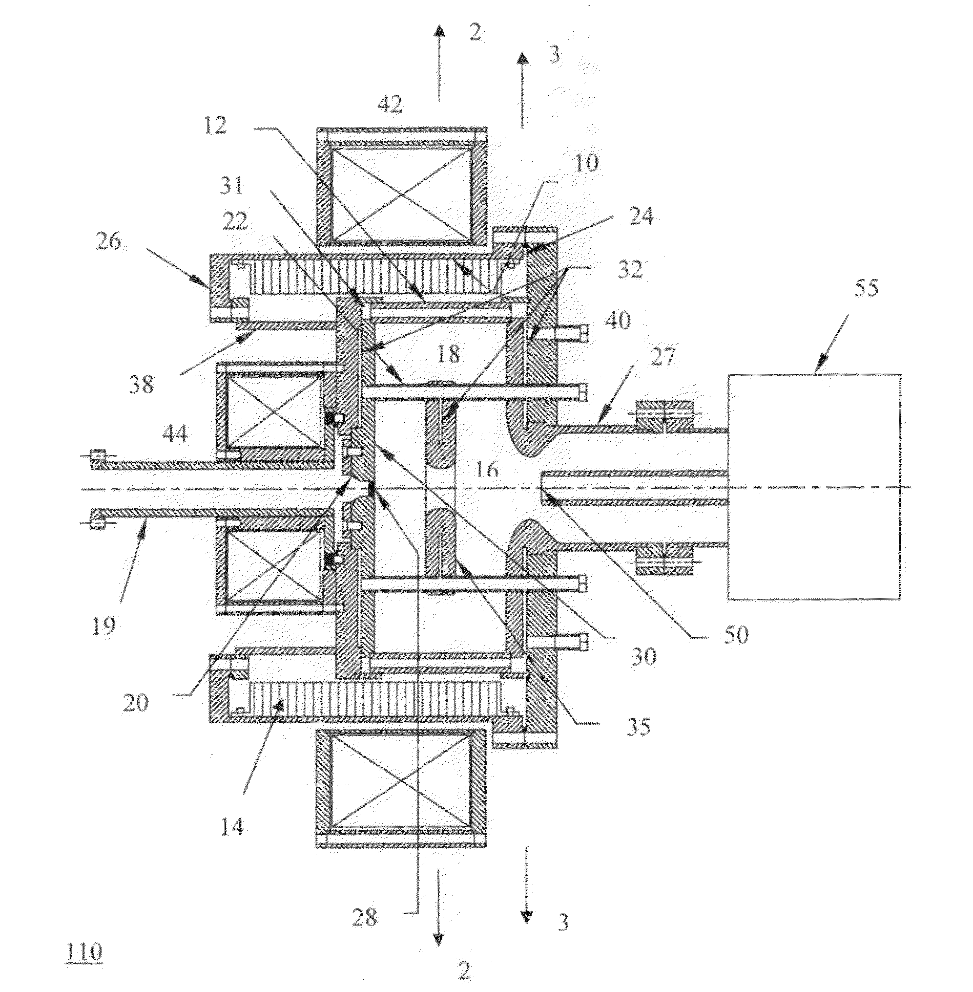
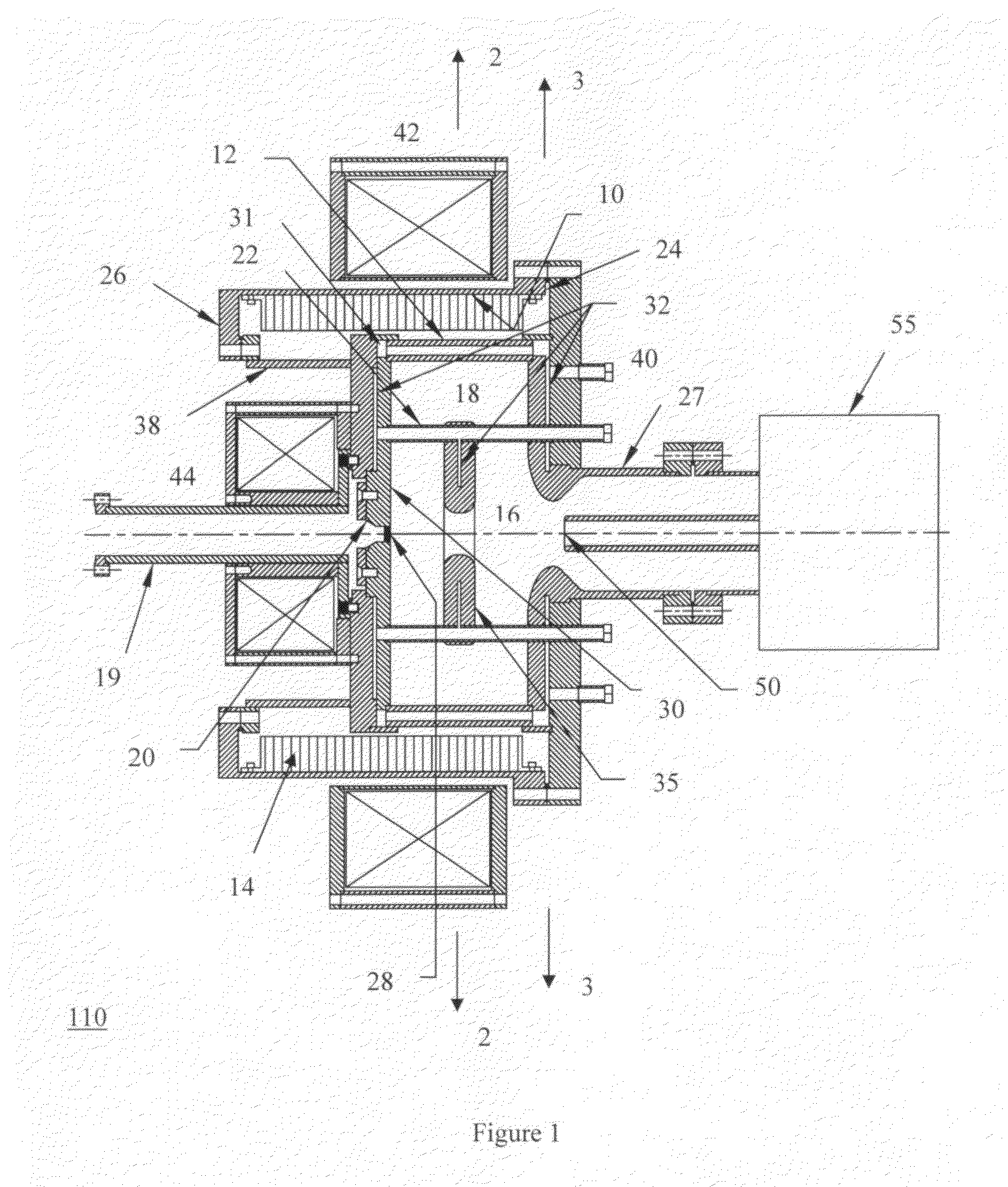
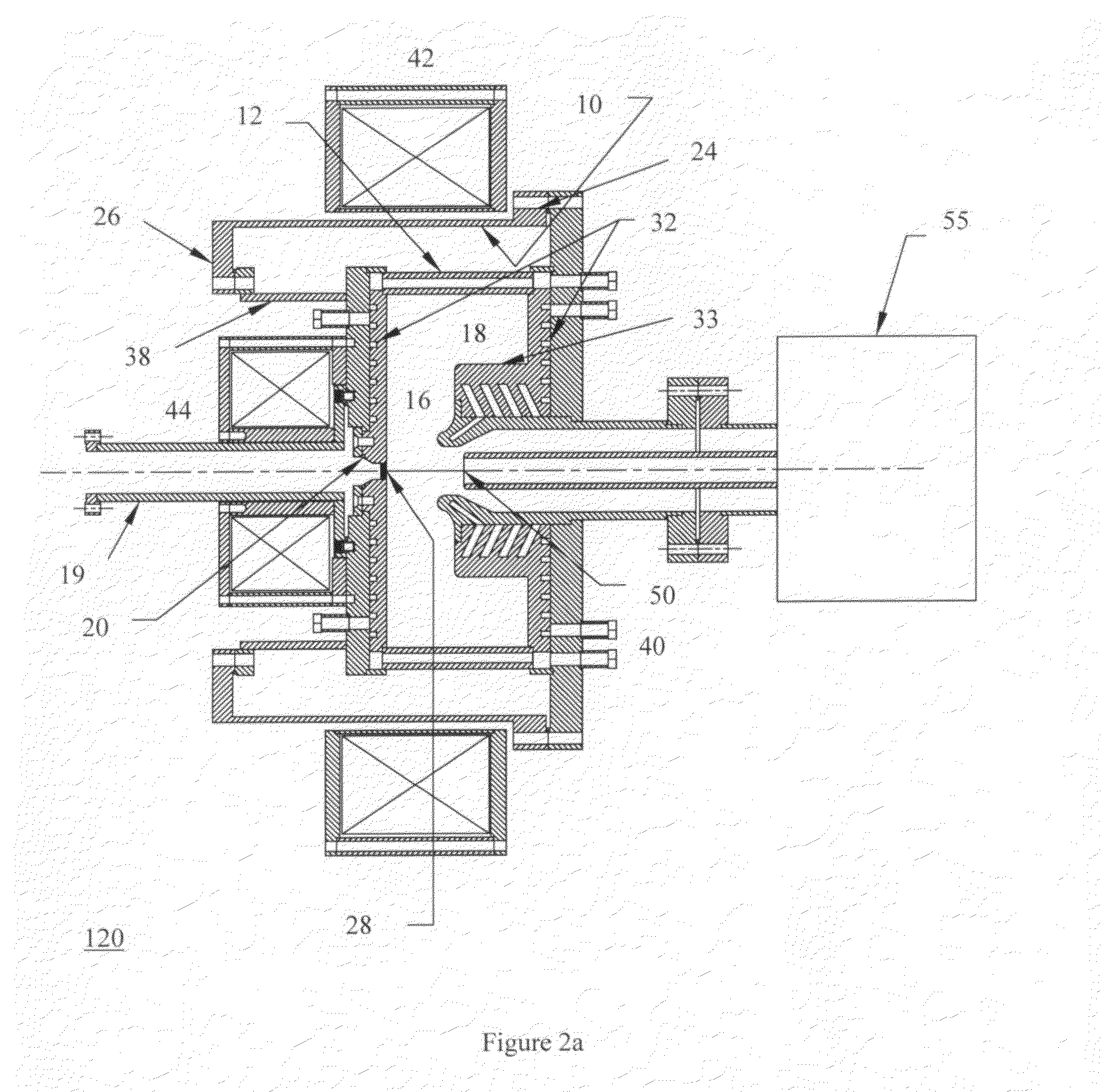
[0020]The ultra high vacuum (UHV) photoelectron linear accelerator (linac) of the present invention with the modified PWT design 110, or hybrid mode design 120, comprises a radiofrequency cavity having a porous outer wall 12 through which is connected a pressure chamber 10 that houses non-evaporative getter (NEG) material 14 for ultra high vacuum pumping. The NEG pumps may be commercially available NEG modules (for example, SAES) 14 mounted on the inside wall of the pressure chamber 10, or a layer of NEG film sputtered directly onto the inside wall of the pressure chamber 10. The removable pressure chamber 10 is attached to the body of the linac 110 or 120 via a standard Conflat flange 24, and a second Conflat flange 26 that is inverted from the standard design. The standard Conflat flange 24 has a bolt circle on the outside of the knife edge. The inverted Conflat flange 26 has a bolt circle on the inside of the knife edge. The mating inverted Conflat flange 26 is optionally connect...


PUM


Abstract

A photoelectron linear accelerator for producing a low emittance polarized electron beam. The linear accelerator includes a tube having a cylindrical wall, said wall being perforated to allow gas to flow to a pressure chamber containing ultra high vacuum pumps located outside the accelerator. The RF accelerator cavity comprises of two concentric cylindrical regions having different outside diameters and different lengths.

Description

GOVERNMENTAL RIGHTS IN INVENTION[0001]This invention was made with partial governmental support under Small Business Innovation Research (SBIR) Contract No. DE-FG02-06ER84460 awarded by the U.S. Department of Energy to DULY Research Inc. The government may have certain rights in the invention.BACKGROUND OF THE INVENTION[0002]1. Field of the Invention[0003]The present invention provides a normal-conducting photoelectron linear accelerator for producing a low-emittance electron beam from a photocathode that operates in ultra high vacuum and under high heat load.[0004]2. Description of the Prior Art[0005]A polarized electron linear accelerator based on a Plane-Wave-Transformer (PWT) design was the subject of a prior U.S. Pat. No. 6,744,226, in which a plurality of iris-loaded disks are suspended by water cooling rods (or pipes) that are connected to two endplates of a cylindrical radiofrequency (RF) cavity. The electric field pattern in the cylindrical PWT cavity is such that a TEM-lik...

Claims


Application Information

Patent Timeline
IPC IPC(8): H05H9/04
CPCH05H7/22H05H2007/122H05H9/048
Inventor YU, DAVID U.L.LUO, YAN
Owner DULY RES
Why Eureka
Try Eureka