Optical Modulator

Active Publication Date: 2012-09-13
SUMITOMO OSAKA CEMENT CO LTD
View PDF30 Cites 8 Cited by
  • Summary
  • Abstract
  • Description
  • Claims
  • Application Information

AI Technical Summary

Benefits of technology

[0012]According to the present invention, there is provided an optical modulator including: a substrate made of a material having an electro-optical effect; an optical waveguide formed on the substrate; and a modulation electrode for having an optical wave propagating through the optical waveguide modulated, wherein emitted light emitted from the optical waveguide is guided by optical fiber, and polarization of the substrate is reversed in a predetermined pattern along the optical waveguide so as to provide waveform distortion having a characteristic opposite to a wavelength dispersion characteristic of the optical fiber. Therefore, if a characteristic opposite to waveform distortion caused by the wavelength dispersion of the optical fiber is provided in advance when the optical modulator converts the electric signal into the optical signal, it is possible to compensate for the deterioration of characteristics even when wavelength dispersion occurs in the optical fiber. In addition, it is possible to compensate for the waveform deterioration without depending on the wavelength and without using digital signal processing technology, therefore it is possible to provide the optical modulator applicable to high-speed transmission over several tens of Gbps.
[0013]According to the

Problems solved by technology

In addition, the optical device of FBG and the like has not only the limitation to operation band of the wavelength but also the large opt

Method used


Image

  • Optical Modulator
  • Optical Modulator
  • Optical Modulator

Examples


Example

[0017]Hereinafter, preferable embodiments of the present invention will be described in detail.

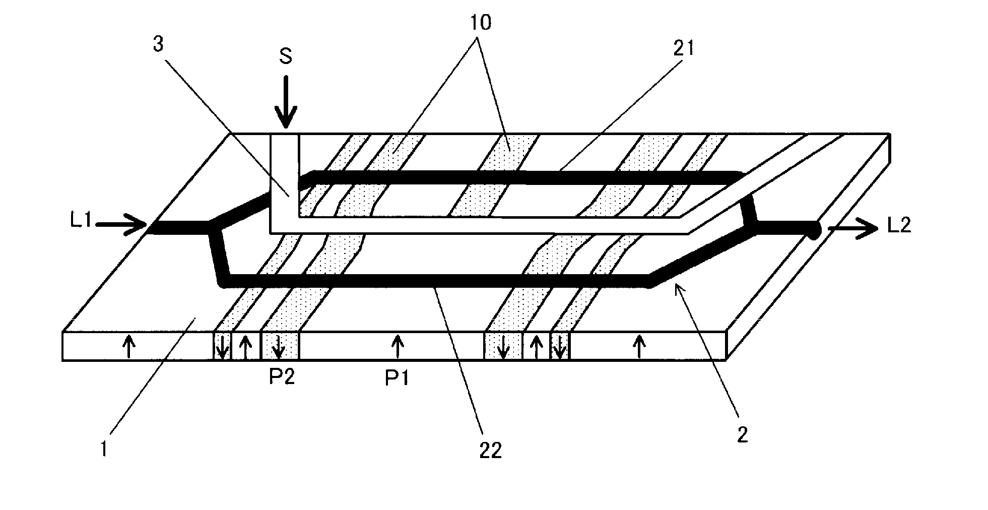
[0018]As shown in FIG. 1, the optical modulator 1 includes a substrate 1 made of a material having an electro-optical effect; an optical waveguide 2 formed on the substrate; and a modulation electrode 3 for modulating an optical wave propagating through the optical waveguide. The emitted light L2 emitted from the optical waveguide is guided by optical fiber (not shown), and polarization of the substrate is reversed 10 in a predetermined pattern along the optical waveguide so as to provide waveform distortion having a characteristic opposite to a wavelength dispersion characteristic of the optical fiber.

[0019]As a substrate using a material having the electro-optical effect of the present invention, it is possible to use the substrate made of, for example, lithium niobate, lithium tantalate, electro optic polymer, and a combination thereof. Particularly, it is preferable that the material h...


PUM


Abstract

An optical modulator includes: a substrate made of a material having an electro-optical effect; an optical waveguide formed on the substrate; and a modulation electrode for modulating an optical wave propagating through the optical waveguide, wherein emitted light emitted from the optical waveguide is guided by optical fiber, and polarization of the substrate is reversed in a predetermined pattern along the optical waveguide so as to provide waveform distortion having a characteristic opposite to a wavelength dispersion characteristic of the optical fiber.

Description

[0001]The present disclosure contains subject matter related to that disclosed in Japanese Priority Patent Application JP 2011-050655 filed in the Japan Patent Office on Mar. 8, 2011, the entire content of which is hereby incorporated by reference.BACKGROUND OF THE INVENTION[0002]1. Field of the Invention[0003]The invention relates to an optical modulator, and more particularly, to an optical modulator for compensating for wavelength dispersion of optical fiber.[0004]2. Description of Related Art[0005]In the fields of optical communication or optical measurement, an optical signal wave modulated in an optical modulator is transmitted in an optical fiber. In the optical fiber, since the propagation velocity of light or the length of the propagation path is different depending on the wavelength, wavelength dispersion occurs and the waveform of the optical signal is distorted. Particularly, waveform distortion is very obvious in the SSMF which is a standard single mode fiber. As a resu...

Claims


Application Information

Patent Timeline
IPC IPC(8): G02F1/035
CPCG02F1/05G02F1/0508G02F2001/3548G02F1/2255G02F2001/212G02F1/3558G02F1/212G02F1/3548
Inventor ICHIKAWA, JUNICHIROOIKAWA, SATOSHIMURATA, HIROSHIOZEKI, YASUYUKI
Owner SUMITOMO OSAKA CEMENT CO LTD
Why Eureka
Try Eureka