Thermal treatment device with variable heat distribution

a treatment device and variable heat technology, applied in the field of thermal treatment devices, can solve the problems of complex sealing, complex manufacturing of such structures, and high specialized filling and sealing equipment, and achieve the effects of reducing side effects, uniform heat, and improving treatment outcomes

Inactive Publication Date: 2012-09-13
JOHNSON & JOHNSON CONSUMER COPANIES
View PDF9 Cites 6 Cited by
  • Summary
  • Abstract
  • Description
  • Claims
  • Application Information

AI Technical Summary

Benefits of technology

[0011]Currently marketed air-activated heat packs provide substantially uniform heat. Providing non-uniform heat distribution may result in better treatment outcomes and decreased side effects. Specifically, sensitization of the user's skin to the sensations of heat can be decreased when the skin is exposed to a heat source of spatially variable temperature. Additionally, higher temperature generating segments might operate for shorter time but provide for a very fast ramp-up of temperature, thus initiating treatment faster, while lower temperature segments might operate for a longer time but provide for a longer ramp-up of temperature, thus initiating treatment slower, but providing for a longer treatment. Thus, it is beneficial to have a non-uniform heat distribution in a heat pack for therapeutic applications. Further, the thermal grill effect, described, for example, in the aforementioned U.S. Application No. 20080140165 to Kimberly-Clark Worldwide, provides for a perceived sensation of heat without exposing the skin to potentially detrimental high temperatures.
[0013]It is an object of the invention to provide a thermal treatment device that comprises variable heat distribution. The thermal treatment device is convenient in that different compositions may be placed into different portions of the thermal treatment device, resulting in a device which provides a hotter portion for a brief burst of time and a warmer portion for a longer portion of time. Typically, air activated heating device compositions are limited, in that the more rapidly the composition oxidizes upon exposure to air, the more rapidly it is extinguished. If a composition is extinguished too rapidly, it cannot provide long-term pain relief. In previous thermal treatment devices, manufacturers have had to compromise between the intensity of the heat and the duration of the heat delivery. It is advantageous to the user to have a device that provides an intense heating portion at the beginning of use, followed by a longer warming device. This can be provided using the device of the present invention.

Problems solved by technology

Additionally, higher temperature generating segments might operate for shorter time but provide for a very fast ramp-up of temperature, thus initiating treatment faster, while lower temperature segments might operate for a longer time but provide for a longer ramp-up of temperature, thus initiating treatment slower, but providing for a longer treatment.
Manufacturing of such structures and particularly filling such structures with different heating mixtures and then sealing such structures is complex and requires highly specialized fill and seal equipment.
Furthermore, the total quantity of the heating material in each heat pack is limited because of the presence of so many sealing areas around each narrow heating element filled with the heating mixture, resulting in low overall amount of heating mixture.
Typically, air activated heating device compositions are limited, in that the more rapidly the composition oxidizes upon exposure to air, the more rapidly it is extinguished.
If a composition is extinguished too rapidly, it cannot provide long-term pain relief.
In previous thermal treatment devices, manufacturers have had to compromise between the intensity of the heat and the duration of the heat delivery.

Method used


Image

  • Thermal treatment device with variable heat distribution
  • Thermal treatment device with variable heat distribution
  • Thermal treatment device with variable heat distribution

Examples


Embodiment Construction

[0021]The following detailed description references the accompanying drawings that show some example aspects of the disclosure. These example aspects are described in sufficient detail to enable those skilled in the art to practice the disclosure. It is to be understood that other aspects may be utilized, or structural changes made, such that the detailed description should not be considered as limiting the scope of the claims.

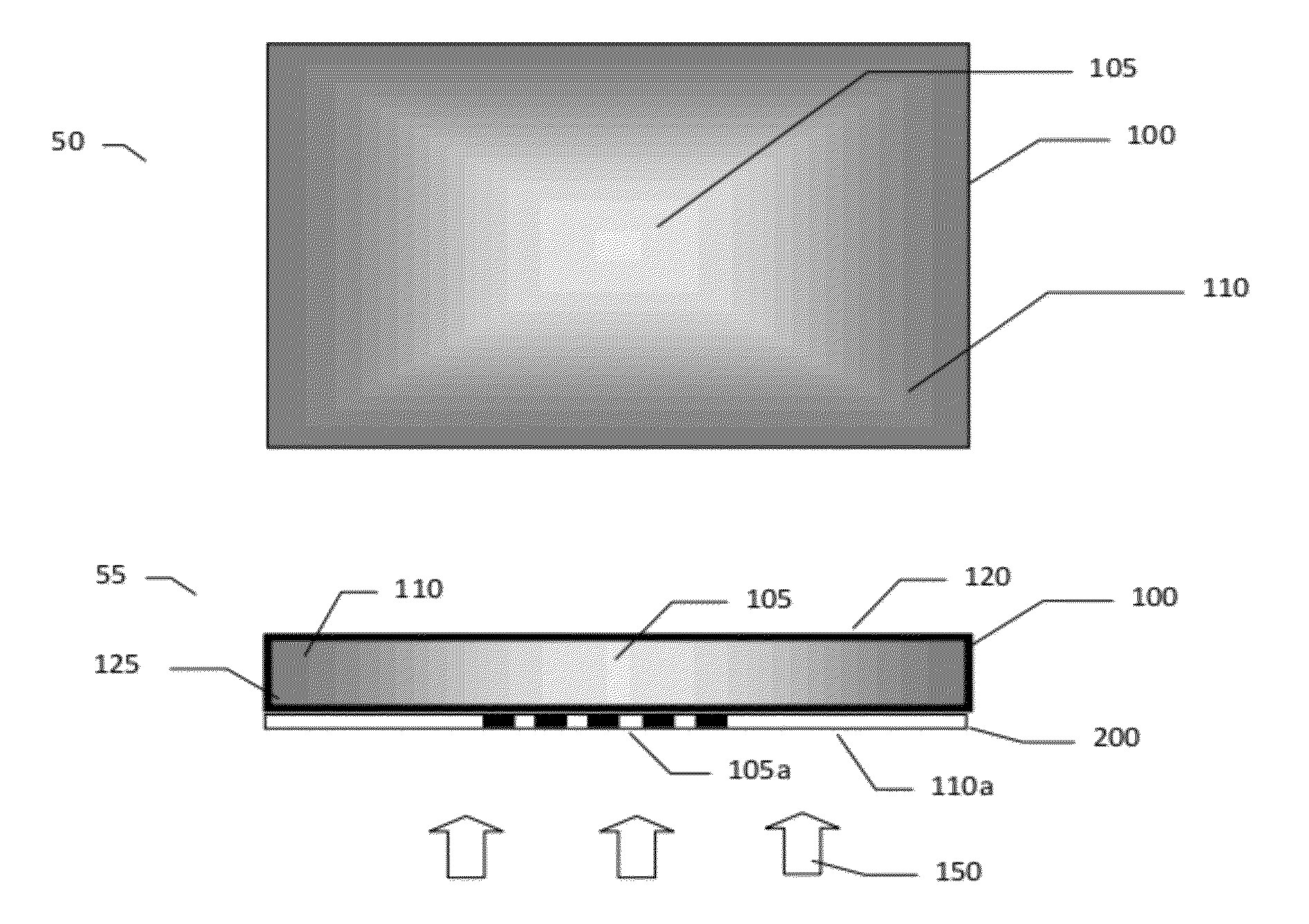
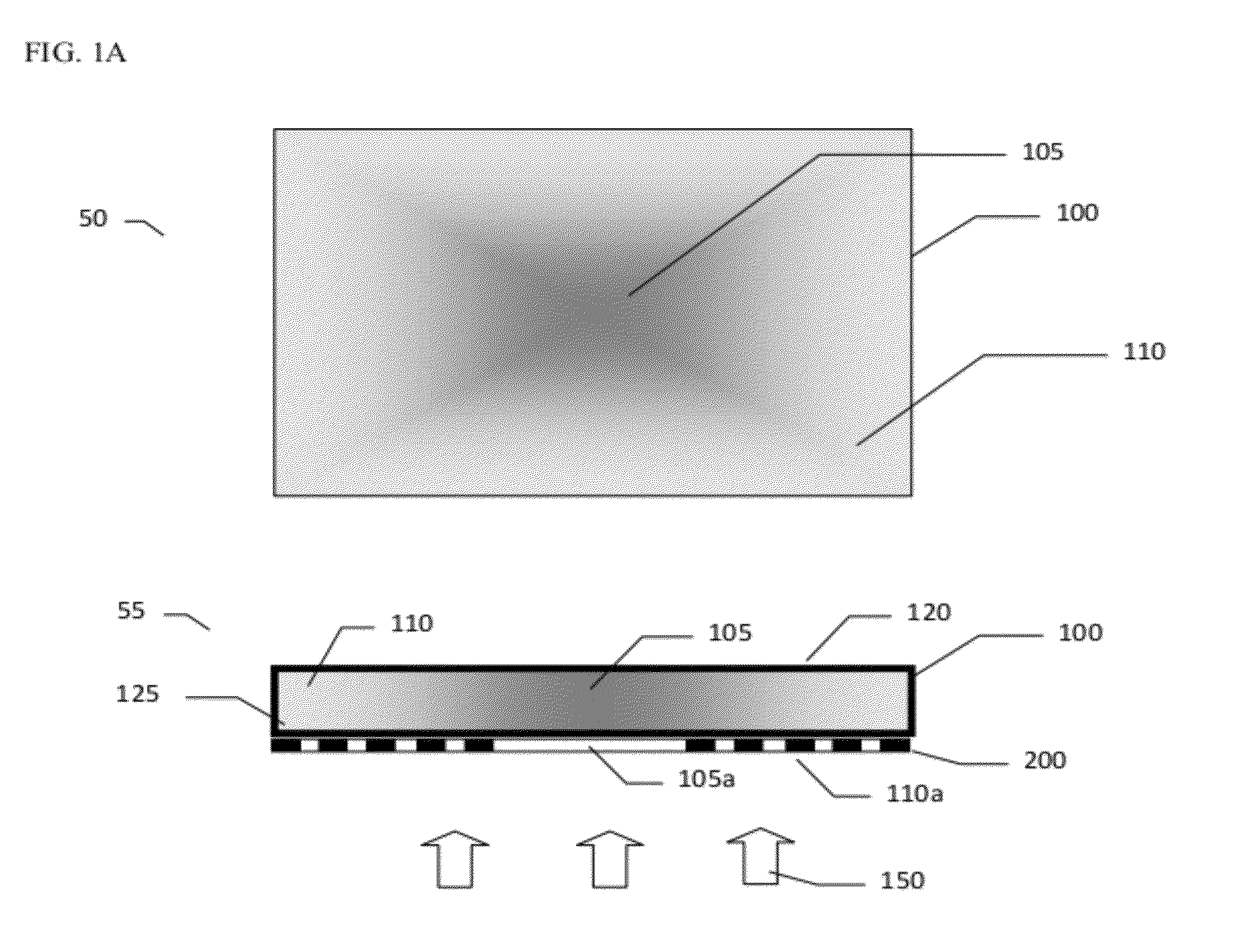
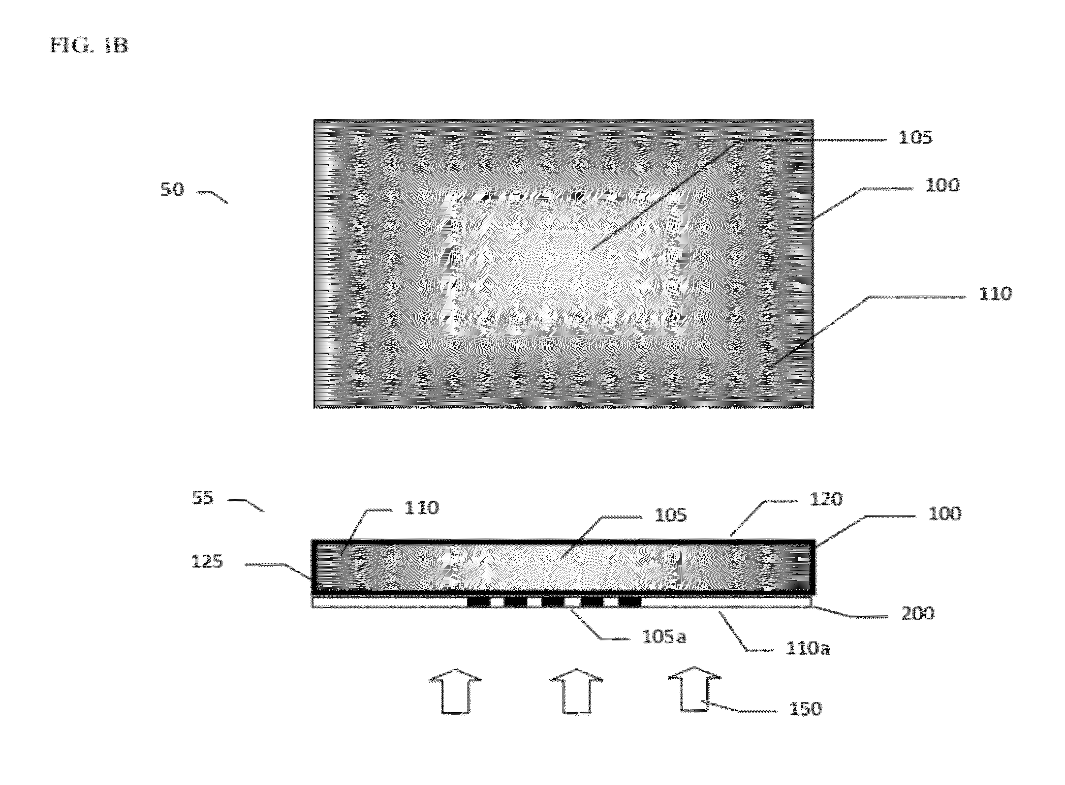
[0022]As used herein, the term “hot” or “hot portion” and its plural, and the term “warm” or “warm portion” and its plural, refer to the portion(s) of the device that are exothermic or potentially exothermic. As used herein, exothermic refers to emitting heat and such heat can be created by a chemical reaction, by electrically-resistive heating, by warmed fluid, or by any other suitable means. The “hot portion” and / or the “warm portion” may actually feel hot and / or warm, respectively, as it would upon activation, or the “hot portion” and / or the “warm portion” ...


PUM


Abstract

A thermal treatment device having variable heat distribution along the device is disclosed.

Description

[0001]This application claims the benefit of U.S. provisional application 61 / 451,312 filed Mar. 10, 2011, the complete disclosure of which is hereby incorporated herein by reference for all purposes.FIELD OF THE INVENTION[0002]The present invention is directed to a thermal treatment device. More particularly, the present invention relates to a thermal treatment device that has variable heat distribution along the device.BACKGROUND OF THE INVENTION[0003]For users with aching muscles and sore joints, the application of heat can loosen stiff muscles, improve blood flow to the affected area, facilitate tissue repair, and create a feeling of relaxation. The application of heat to the skin has historically been used for pain relief of muscles and joints, as well as for the treatment of certain inflammatory conditions. The application of cold materials to the skin has also been used for similar treatments, especially for treating inflammatory responses such as joint inflammation.[0004]Chem...

Claims


Application Information

Patent Timeline
Patent Type & Authority Applications(United States)
IPC IPC(8): A61F7/08
CPCA61F7/034A61F2007/0242A61F2007/0295A61F2007/0249A61F2007/0268A61F2007/0246
Inventor KRIKSUNOV, LEO B.WYNN, DAVID W.
Owner JOHNSON & JOHNSON CONSUMER COPANIES
Why Eureka
Try Eureka