Conductive foils having multiple layers and methods of forming same

Inactive Publication Date: 2012-09-20
APPLIED MATERIALS INC
View PDF6 Cites 34 Cited by
  • Summary
  • Abstract
  • Description
  • Claims
  • Application Information

AI Technical Summary

Benefits of technology

[0007]Embodiments of the invention generally relate to conductive foils having multiple layers for use in photovoltaic modules and methods of forming the same. The conductive foils generally include a layer of aluminum foil having one or more metal layers with decreased contact resistance disposed thereon. An anti-corrosion material and a dielectric material are generally disposed on the upper surface of the metal layer. The conductive foils may be formed on a carrier prior to

Problems solved by technology

The conductive circuit is usually formed from copper, which is a relatively expensive material, and thus represents a sizeable portion of the tot

Method used


Image

  • Conductive foils having multiple layers and methods of forming same
  • Conductive foils having multiple layers and methods of forming same
  • Conductive foils having multiple layers and methods of forming same

Examples


Embodiment Construction

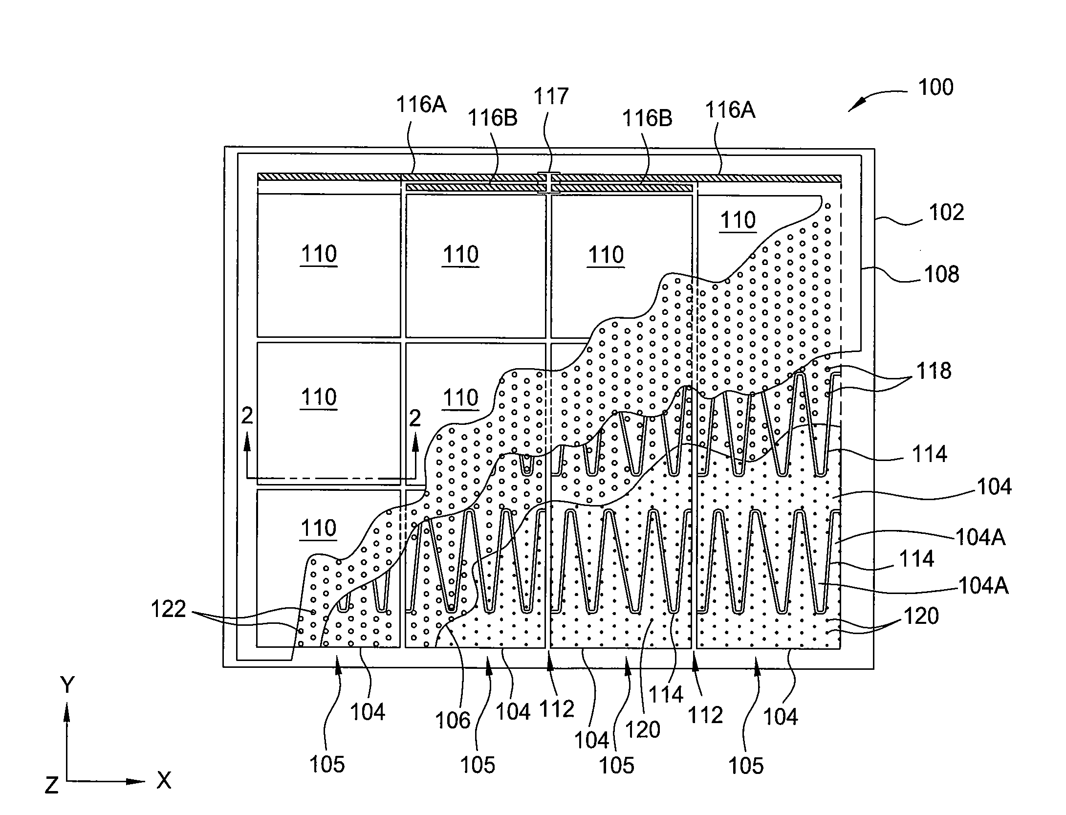
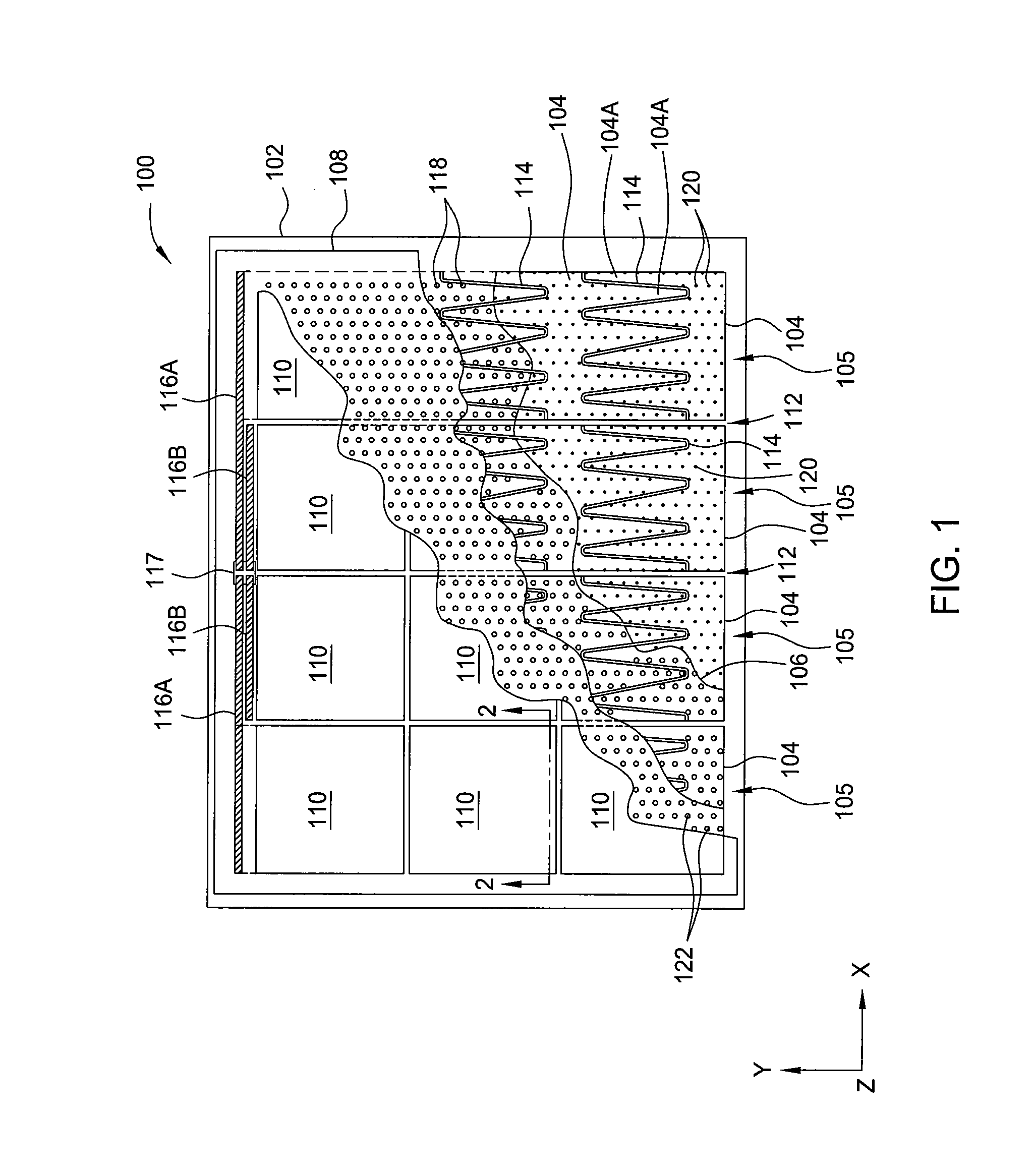
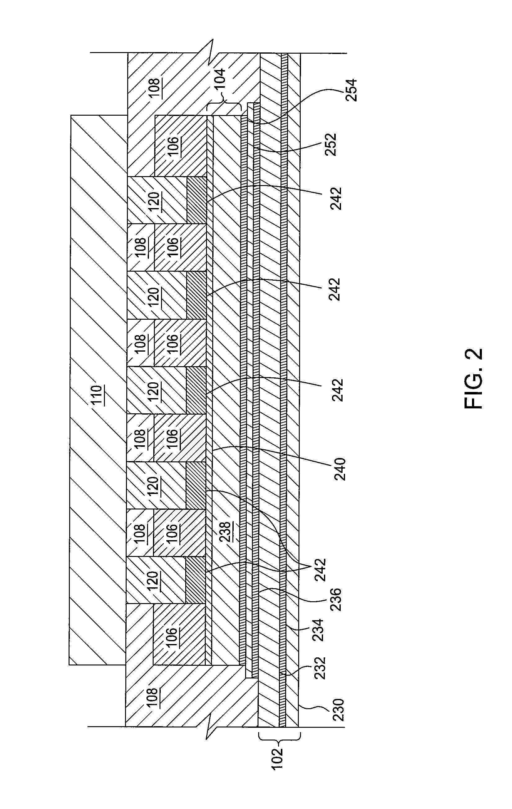
[0019]Embodiments of the invention generally relate to conductive foils having multiple layers for use in photovoltaic modules and methods of forming the same. The conductive foils generally include a layer of aluminum foil having one or more metal layers with decreased contact resistance disposed thereon. An anti-corrosion material and a dielectric material are generally disposed on the upper surface of the metal layer. The conductive foils may be formed on a carrier prior to construction of a photovoltaic module, and then applied to the photovoltaic module as a conductive foil assembly during construction of the photovoltaic module. Methods of forming the conductive foils generally include adhering an aluminum foil to a carrier, removing native oxides from a surface of the aluminum foil, and sputtering a metal onto the aluminum foil. A dielectric material and an anti-corrosion material may then be applied to the upper surface of the sputtered metal.

[0020]FIG. 1 is a top plan view ...


PUM

PropertyMeasurementUnit
Lengthaaaaaaaaaa
Corrosion propertiesaaaaaaaaaa
Electrical conductoraaaaaaaaaa

Abstract

Embodiments of the invention generally relate to conductive foils having multiple layers for use in photovoltaic modules and methods of forming the same. The conductive foils generally include a layer of aluminum foil having one or more metal layers with decreased contact resistance disposed thereon. An anti-corrosion material and a dielectric material are generally disposed on the upper surface of the metal layer. The conductive foils may be formed on a carrier prior to construction of a photovoltaic module, and then applied to the photovoltaic module as a conductive foil assembly during construction of the photovoltaic module. Methods of forming the conductive foils generally include adhering an aluminum foil to a carrier, removing native oxides from a surface of the aluminum foil, and sputtering a metal onto the aluminum foil. A dielectric material and an anti-corrosion material may then be applied to the upper surface of the sputtered metal.

Description

CROSS-REFERENCE TO RELATED APPLICATIONS[0001]This application claims benefit of U.S. provisional patent application Ser. No. 61 / 487,599 [Atty. Dkt. No. APPM / 16284L], filed May 18, 2011, and U.S. Provisional Patent Application Ser. No. 61 / 454,382 [Atty. Dkt. No. APPM / 16122L], filed Mar. 18, 2011, which are both herein incorporated by reference.BACKGROUND OF THE INVENTION[0002]1. Field of the Invention[0003]Embodiments of the invention generally relate to conductive foils used in the manufacture of photovoltaic modules having back-contact cells and methods of producing the same.[0004]2. Description of the Related Art[0005]Solar cells are photovoltaic devices that convert sunlight into electrical power. Each solar cell generates a specific amount of electric power and is typically tiled into an array of interconnected solar cells that are sized to deliver a desired amount of generated electrical power. The generated electrical power is transported from the solar cells to a junction box...

Claims


Application Information

Patent Timeline
IPC IPC(8): H05K1/09C23C14/34
CPCC23C14/34H05K1/09H01L31/049Y02E10/50H01L31/022441H01L31/0516B32B15/04
Inventor BOTTENBERG, WILLIAMTELLE, JOHNMEAKIN, DAVID H.MURPHY, BRIAN J.
Owner APPLIED MATERIALS INC
Why Eureka
Try Eureka