Voltage controlled oscillator circuits and methods using variable capacitance degeneration for increased tuning range

a voltage control and oscillator technology, applied in the direction of oscillator, pulse technique, pulse generator, etc., can solve the problems of increased phase noise, increased loss of tank circuit, and trade-off between tuning range and phase noise, so as to increase the parasitic resistance rp, increase the tuning range and oscillation frequency of an lc vco, and reduce power

Inactive Publication Date: 2012-09-20
IBM CORP
View PDF3 Cites 10 Cited by
  • Summary
  • Abstract
  • Description
  • Claims
  • Application Information

AI Technical Summary

Benefits of technology

[0013]By employing fixed capacitive degeneration, the tuning range and oscillation frequency of an LC VCO can be increased, with less power required to sustain oscillation. Despite this advantage, however, the performance of a VCO with fixed capacitive degeneration can be degraded under different bias conditions due to changes (increase or decrease) in the parasitic resistance RP of the LC tank under such varying bias conditions. For instance, with the the conventional VCO framework of FIG. 2, depending of the type of varactors in the tank circuit (22) and the polarity of Vtune, a change in the bias conditions can increase the parasitic resistance Rp of the LC tank (22) (more energy being absorbed in the tank) which can suppress oscillation.
[0014]In general, exemplary embodiments of the invention include voltage controlled oscillator circuits employing variable capacitance degeneration to provide increased tuning ranges and output amplitudes for VCOs for use in millimeter wave applications. Exemplary embodiments of the invention include methods for utilizing variable capacitance degeneration for tuning / controlling VCO gain and the parasitic behaviors of active devices of the oscillator core, to thereby provide increased tuning range and output power across the full bandwidth of the oscillator at mllimeter wave operating frequencies.

Problems solved by technology

When designing a VCO, however, there is typically a tradeoff between tuning range and phase noise.
An increase in the capacitance C, however, results in increased loss of the tank circuit (12).
The increase in loss may be offset by increasing the gain of the VCO circuit (10), but an increase in gain has the adverse effect of amplifying noise in the input signal to the VCO, resulting in increased phase noise.
Decreasing the inductive load L, however, decreases the quality of the tank and thereby increases the phase noise.

Method used


Image

  • Voltage controlled oscillator circuits and methods using variable capacitance degeneration for increased tuning range
  • Voltage controlled oscillator circuits and methods using variable capacitance degeneration for increased tuning range
  • Voltage controlled oscillator circuits and methods using variable capacitance degeneration for increased tuning range

Examples


Embodiment Construction

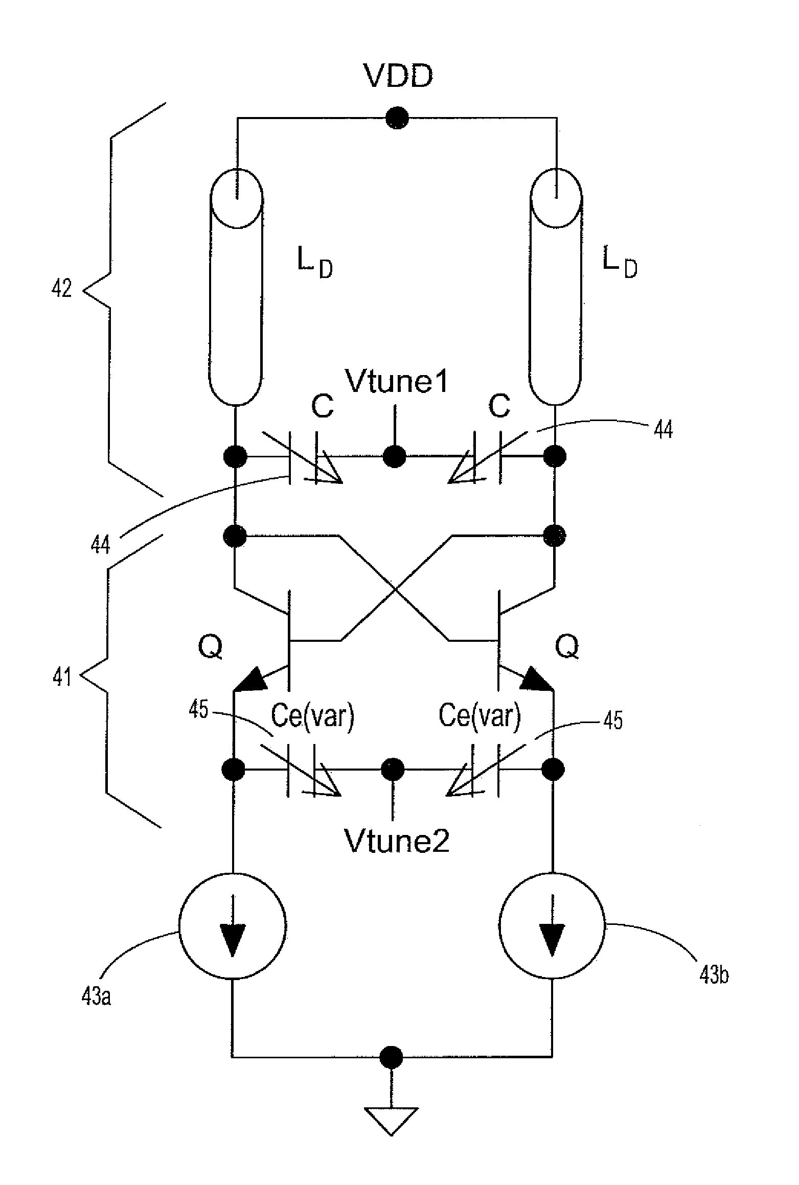
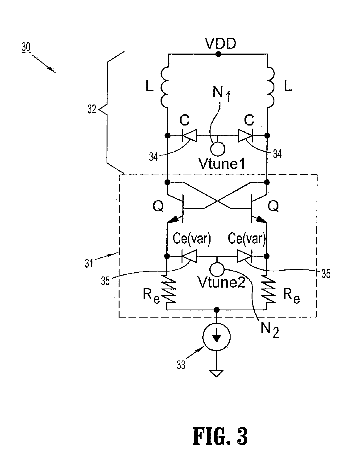
[0021]FIG. 3 schematically illustrates a voltage controlled oscillator with variable capacitance degeneration according to an exemplary embodiment of the invention. In particular, FIG. 3 illustrates an LC VCO circuit (30) which generally comprises an oscillator core (31), a resonant circuit (32) and a current source (33). The oscillator core (31) comprises a feedback circuit to compensate losses of the resonant circuit (32). As depicted in FIG. 3, the feedback circuit may be implemented using a pair of cross-coupled transistors Q (e.g., bipolar junction transistors or other types of transistors depending on the application). The resonant circuit (32) and current source (33) can be implemented using known circuit topologies.

[0022]The resonant circuit (32) may include parallel inductors L and variable capacitors C. The variable capacitors C are connected between the collector terminals of the transistors Q and commonly connected to a tuning voltage (Vtune1) input node N1. In one exemp...


PUM


Abstract

Voltage controlled oscillator circuits are provided in which variable capacitance degeneration is employed to provide increased tuning ranges and output amplitudes for VCO circuits for millimeter wave applications.

Description

CROSS REFERENCE TO RELATED APPLICATIONS[0001]This application is a Divisional Application of U.S. application Ser. No. 11 / 619,765, filed on Jan. 4, 2007, which is incorporated by reference herein in its entirety.TECHNICAL FIELD OF THE INVENTION[0002]The present invention relates generally to circuits and methods for implementing VCO (voltage controlled oscillator) circuits for millimeter wave applications. More specifically, the invention relates to circuits and methods for constructing LC voltage controlled oscillators using variable capacitance degeneration to provide increased tuning ranges for millimeter wave applications.BACKGROUND[0003]In general, a VCO (voltage controlled oscillator) is an oscillator circuit that outputs an AC signal having a frequency that varies in response to an input control voltage. VCOs are fundamental components that are employed in a broad range of applications including radar and communications systems (e.g., wireline or wireless applications) for da...

Claims


Application Information

Patent Timeline
Patent Type & Authority Applications(United States)
IPC IPC(8): H03B5/12
CPCH03B5/1231H03B5/1243H03B5/1215
Inventor PFEIFFER, ULLRICH R.WELCH, BRIAN
Owner IBM CORP
Why Eureka
Try Eureka